Remote Interface Devices for Express
This section covers the installation of the RIU and RVI devices with your system. For information about installing ETCNet2 devices, including the ETCNet2 DMX Node and ETCNet2 Video Node, consult the separate Installation Guides for those products.
Install a Remote Interface Unit or Remote Video Interface as follows:
- Connect the network cable to the RJ45 twisted pair connector.123
- Plug the power cable into a grounded power outlet.
- Set DIP switches and/or installing jumpers, as appropriate.
- Install Remote Unit software (see Upgrading remote interface devices) for a discussion and procedure.
121 If using an older console and thinnet wiring, please see Using thinnet with older consoles, for information and instructions.
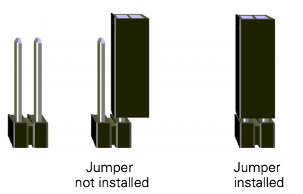
Installing jumpers
A jumper is a small plastic connector used to join a pair of pins sticking out of a printed circuit board. The jumper is installed when it covers both pins. It is not installed when it covers one or none of the pins (see illustration below).
Remote Interface Unit (RIU)
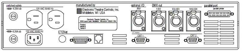
The illustration below shows the RIU’s back panel and indicates the connector used by each accessory. The front panel includes a connector for a digitizer (not used with Express consoles) and an alphanumeric keyboard.
The RIU back panel contains connectors for up to two monitors (only CRT 1 is active), three DMX512 outputs and an RFU.
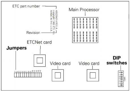
RIU DIP switch and jumper settings
The RIU’s main circuit board contains one 8-switch DIP at location S1 and a set of 14 jumpers at location J22, as shown in the illustration below.
- Remove the screws that secure the top panel.
- Raise the top panel to expose the internal circuitry.
- Locate the DIP switches at location S1 on the corner of the circuit board nearest the power switch. Switches are either On (Closed) or Off (Open). DIP switch 1 must be Off and 2 must be On or the Remote Interface will not start. Adjust the settings as necessary to match the following table.
| DIP Switch | Position | Function |
|---|---|---|
| 1 | Off (Open) | Normal operation, Factory Use Only |
| 2 | On (Closed) | Normal operation, Factory Use Only |
| 3 | Off (Open) | Normal operation, Factory Use Only |
| 4 | Off (Open) | Normal operation, Factory Use Only |
| 5 | Off (Open) | Normal operation, Factory Use Only |
| 6 | Off (Open) | Normal operation, Factory Use Only |
| 7 | Off (Open) | Normal operation, Factory Use Only |
| 8 | Off (Open) | Normal operation, Factory Use Only |
- Locate jumpers 1 through 14. (location J22)
- Jumper 13 must always be off. Jumper 14 should always be installed.
- Install jumpers 7 through 12. Be certain jumpers 1 through 6 are not installed.124
- Close the face panel and replace the screws.
- The Remote Interface checks DIP switch settings when it is turned on. Restart the unit for new DIP switch settings to take effect.
Replacing RIU fuses
The Remote Interface unit contains two pop-out 6.25 Amp fuses at the left side of the rear panel. Inspect and replace as explained below.
- Turn off the device.
- Remove the power cord.
- Pull the fuse tray out of its holder by placing something sharp behind the tab on the bottom of the cover. The tray remains connected to the tray holder but rotates downward for convenience.
- CAUTION: Operate the tray carefully to avoid damage.
- Examine both fuses. Telltale signs of a blown fuse include discoloration or deposits on the glass envelope and/or a visibly broken fuse strip.
- If you find a blown fuse, replace it with the fuse of the same type and size.
- With good fuses installed, rotate the tray up and inward until it is again flush with the panel.
- Replace the power cord and check the console for proper operation. If still having problems, see Help from ETC Technical Services, page 11, to get assistance from ETC.
Remote Video Interface (RVI)
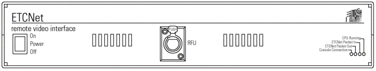
The Remote Video Interface provides ports for remote accessories. It supports one monitor (the connector labeled CRT 1 is active), an alphanumeric keyboard and an RFU, and provides a serial port for a digitizer (digitizer not used with Express). The illustrations below show the RVI’s front and back panels and indicate the connector used by each accessory.
ETCNet Remote Video Interface back panel
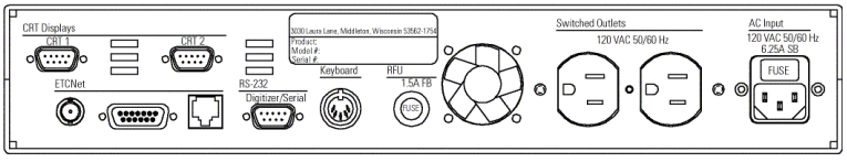
ETCNet Remote Video Interface front panel
Fuses
The RVI contains a 6.25 Amp power fuse in a recessed tray at the right side of the rear panel. Inspect and replace this fuse as explained in the section above entitled Replacing RIU fuses.
The RVI unit also contains a 1.5 Amp fuse to protect the RFU circuit. This fuse is contained in a pop-out receptacle located near the middle of the rear panel. Inspect and replace this fuse as explained under External device fuse.
Remote Video Interface settings
The RVI Processor Board is the lower circuit board in the Remote Video Interface (RVI). It contains one 8-switch DIP. Under normal conditions, these switches will never need to be changed.
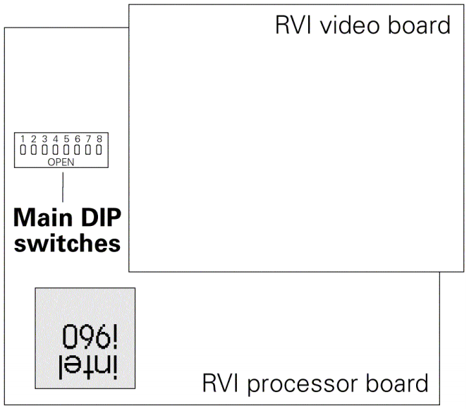
If the settings get changed and you need to restore them, find the switches at location S4 and adjust the settings as listed below. The RVI checks DIP switch settings when the unit is turned on. You must restart the unit for the new settings to take effect.
| DIP Switch | Position | Function |
|---|---|---|
| 1 | On (Closed) | Normal operation, Factory Use Only |
| 2 | Off (Open) | Normal operation, Factory Use Only |
| 3 | Off (Open) | Normal operation, Factory Use Only |
| 4 | Off (Open) | Normal operation, Factory Use Only |
| 5 | Off (Open) | Normal operation, Factory Use Only |
| 6 | On (Closed) | Normal operation, Factory Use Only |
| 7 | On (Closed) | Normal operation, Factory Use Only |
| 8 | Off (Open) | Normal operation, Factory Use Only |
Switches are either On (Closed) or Off (Open).
RVI ETCNet DIP switch settings
In order to enable the RVI for use on the ETCNet network, you must verify or adjust the settings of two sets of DIP switches. You will need to use a pin or a similar fine-pointed object to set the switches.
To set the switches, follow these steps.
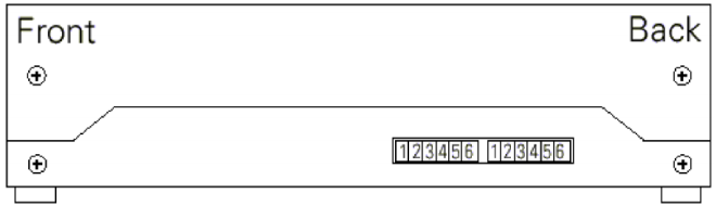
- Locate the two sets of DIP switches, visible through the right side panel of the RVI. See the drawing below.
- Set all six switches of the DIP closest to the front of the RVI to the Off position (up). Set all six switches of the DIP closest to the back of the RVI to the On position (down).125
Installing remote video monitors
You can have additional monitors at remote locations. Connect them to RIUs or RVIs operating on ETCNet. These remote monitors duplicate the console’s displays.
Connect monitors to interface devices by following these steps.
- Insert the female end of the monitor power cord in the monitor connector, and the male end of the monitor power cord in the interface device connector labeled Switched outlets.
- Connect the cable to the connector labeled CRT 1.
- Turn monitor power switch to its On position.
VGA monitor console connector
HD-DB15 female
VGA monitor pinout
- Red video
- Green video
- Blue video
- Ground
- Ground
- Red ground
- Green ground
- Blue ground
- not connected
- Ground
- Ground
- not connected
- Horizontal (H/V) sync
- Vertical sync
- not connected
125 If using an older console and thinnet wiring, please see Using thinnet with older consoles, for different DIP switch settings.
124 If using an older console and thinnet wiring, please see Using thinnet with older consoles, for different jumper arrangements.
123 If using an older console and thinnet wiring, please see Using thinnet with older consoles, for information and instructions.