DAS Satellite Station Info
Overview
1065B5006 – Satellite station
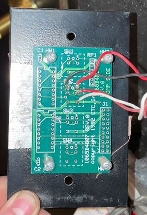
Used to connect external contacts and pots to a DAS system. Sometimes used to connect DAS-style stations that have had their electronics stripped and are raw PCBs with the switches + lamp only.

A DAS station designed to connect to a Satellite Station. The red and black wires land on the contact, and the red and white wires land on the LED.
1065B5006

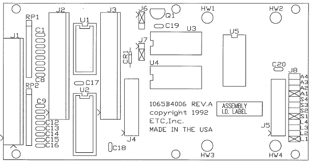
1065B5006 PCB diagram
Jumpers should be installed on A1, S1, and L1.
J2 has switch inputs, J3 has LED outputs. J1 is used for fader inputs.
J5 connects the station to a standard DAS electronics board which should be wired as standard to the rest of the system.
Field Wiring Pinouts
| Pin | J1 (Fader In), J2 (Momentary Contact In), J3 (LED Out) |
| 1 | COM |
| 2 | COM |
| 3 | +5VDC |
| 4 | +5VDC |
| 5 | Ch 8 |
| 6 | Ch 7 |
| 7 | Ch 6 |
| 8 | Ch 5 |
| 9 | Ch 4 |
| 10 | Ch 3 |
| 11 | Ch 2 |
| 12 | Ch 1 |
