Setting Up a Loaner Echo Power Control Processor (E-PCP)
Echo Power Control Processors require a configuration to function.
Ensure that power to the rack is disconnected before removing any components. Failure to do so can result in damage to your equipment or personal injury.
Panel Types
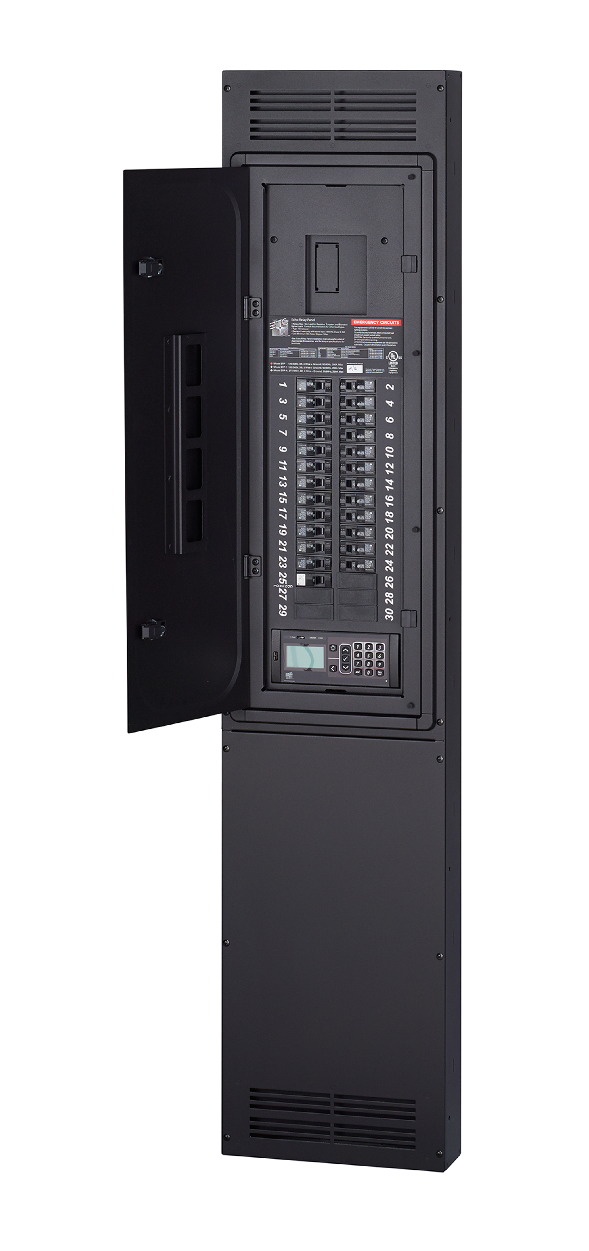
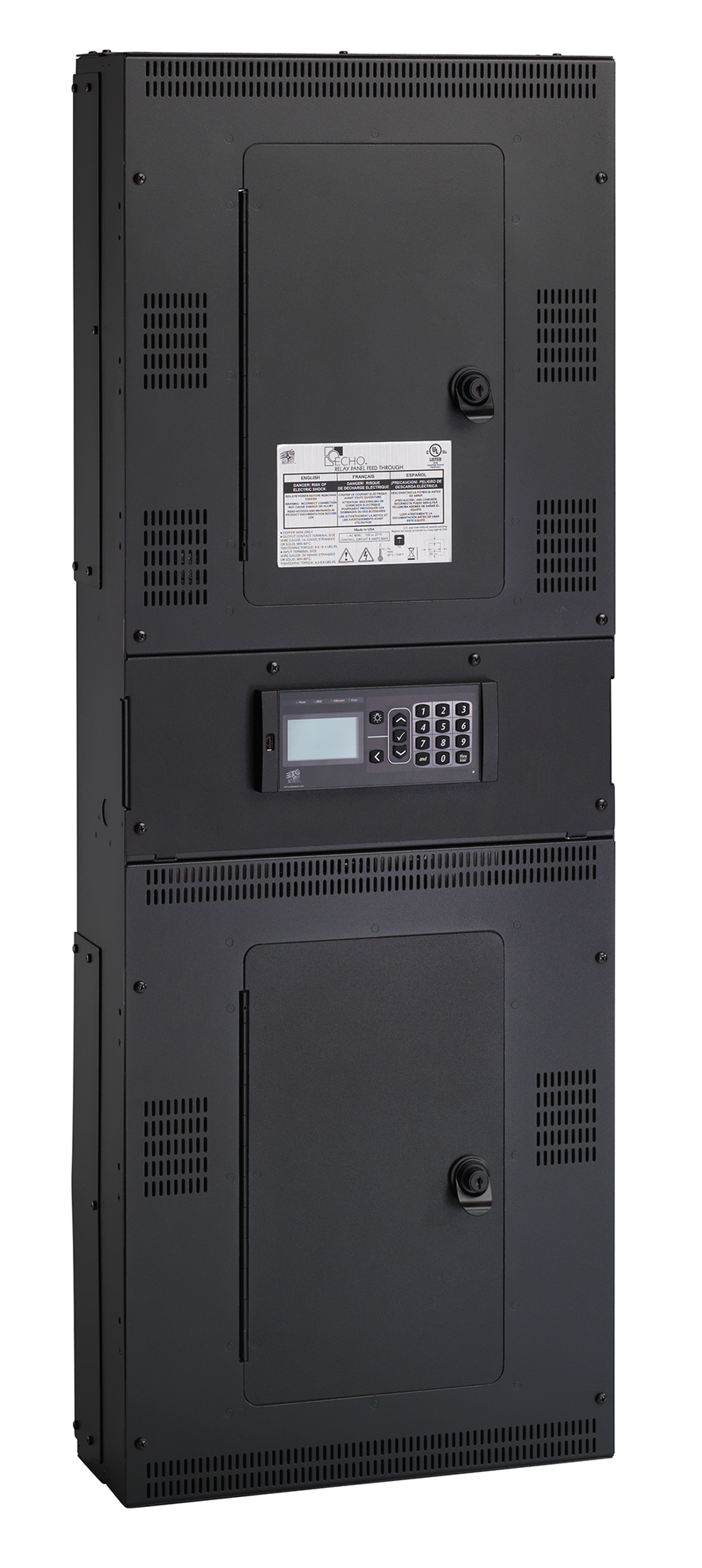
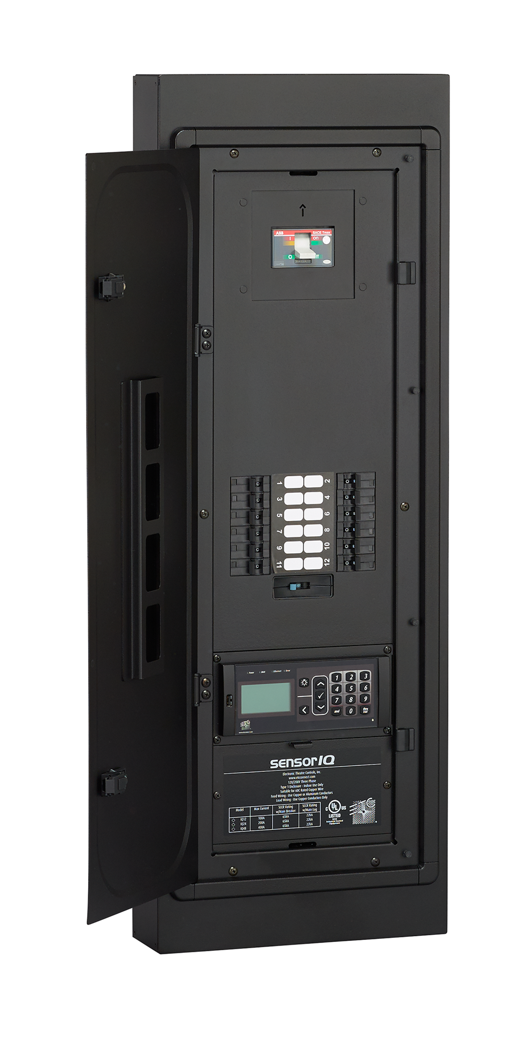
The Echo Power Control Processor (E-PCP) is used in three types of panel, shown below. First, determine which type of panel you have. Please note that the panel size and number of breakers may vary from the photos below.
| Echo Relay Panel (ERP) Mains Fed | Echo Relay Panel Feed Through (ERP-FT) | Sensor IQ |
|---|---|---|
 |
 |
 |
Processor Types
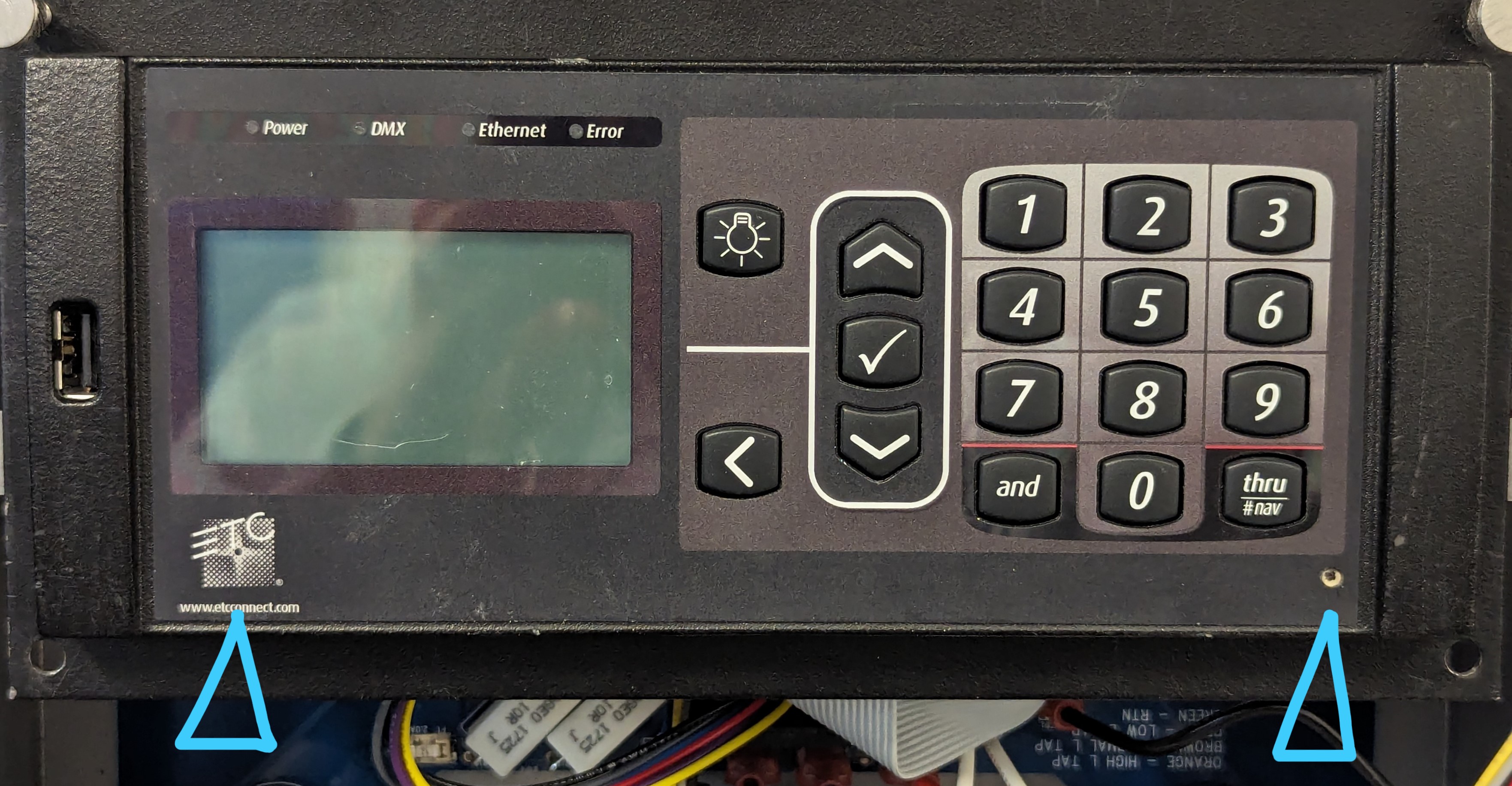
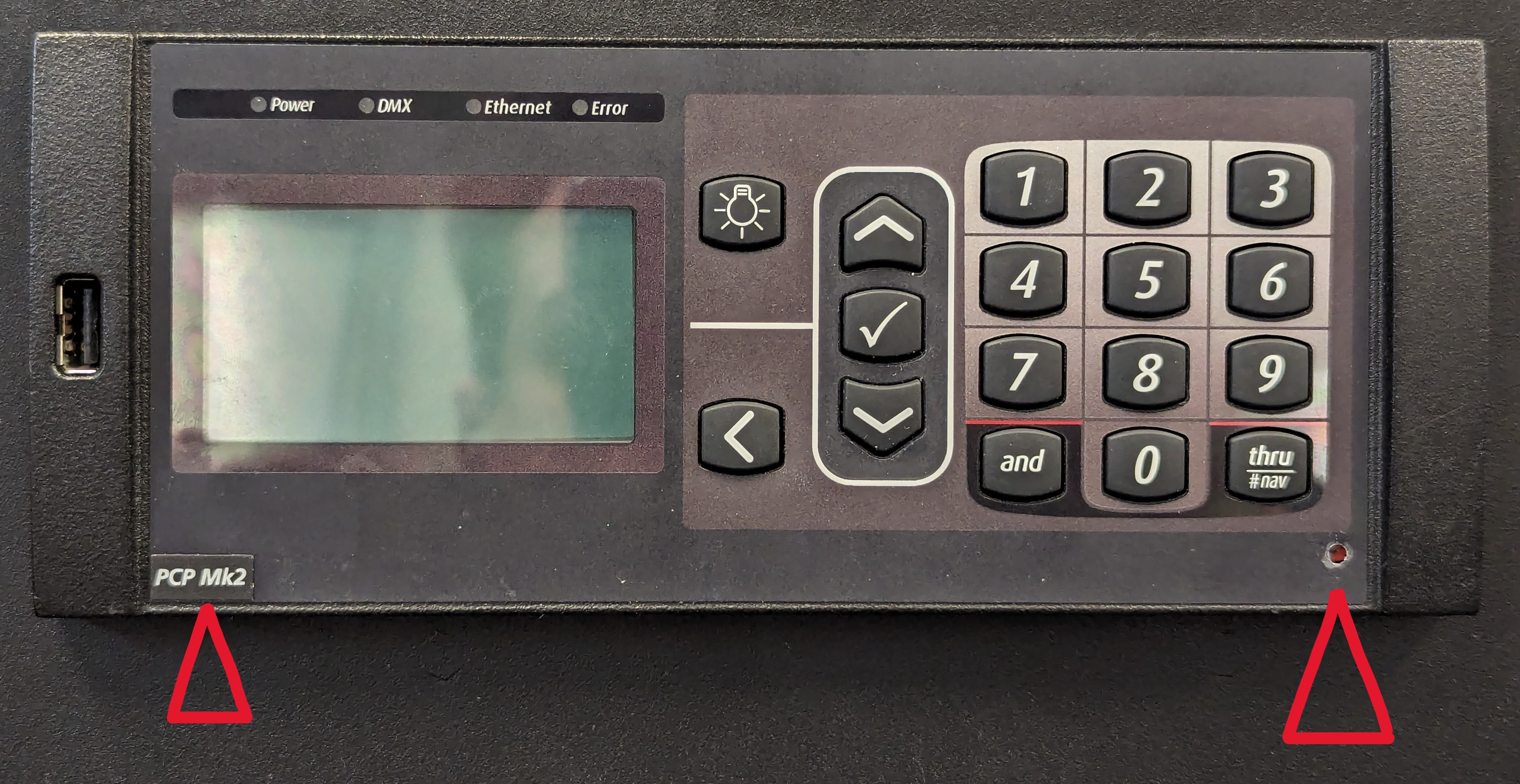
There are two revisions of the Echo Power Control Processor, referred to as E-PCP Mk1 and PCP Mk2. The loaner installation process is different for each type. Mk1 and Mk2 can be distinguished via the label below the screen, the color of the recessed reset button, or the firmware version number. Determine if your panel has a Mk1 or Mk2 PCP.
| E-PCP Mk1 | PCP Mk2 |
|---|---|
 |
 |
|
|
Saving the Configuration
If your E-PCP is still functional, you can save its configuration to USB and then load it to the loaner. If your E-PCP is not functional, you can skip this step, but you will need to manually rewrite the configuration on the loaner.
Installing the Loaner
Ensure that power to the rack is disconnected before removing any components. Failure to do so can result in damage to your equipment or personal injury.
Remove the E-PCP
- If necessary, remove the panel deadfront to access the E-PCP assembly.
- Remove the four screws attaching the mounting plate to the panel, then pull the mounting plate away from the control enclosure.
- Remove the four screws on the backside of the mounting plate attaching it to the E-PCP.
- Take note of how all wiring harnesses between the panel and E-PCP are connected, then carefully disconnect all wiring harnesses from the E-PCP.
Install the Loaner
- Attach the loaner E-PCP to the mounting plate using the same four screws.
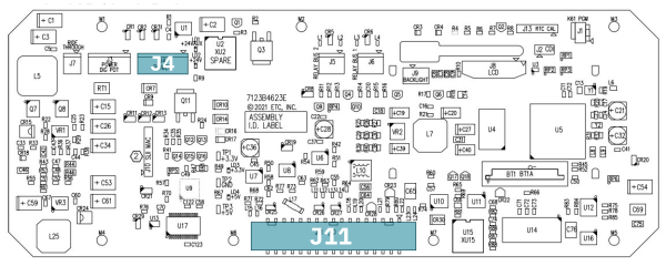
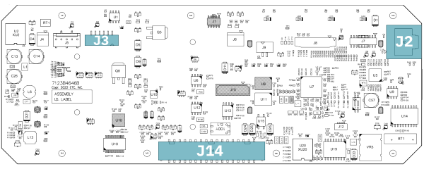
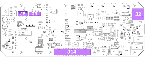
- Connect the wiring harnesses between the E-PCP and the panel according to the diagram below.
- Some panels may have additional harnesses installed for optional features; connect harnesses to the loaner the same way they were connected originally.
| ERP Mains Fed | ERP Feed Through | Sensor IQ | |
|---|---|---|---|
| Mk1 | 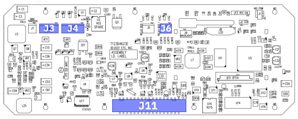 |
 |
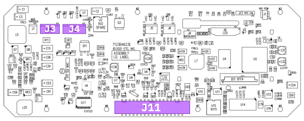 |
| Mk2 | 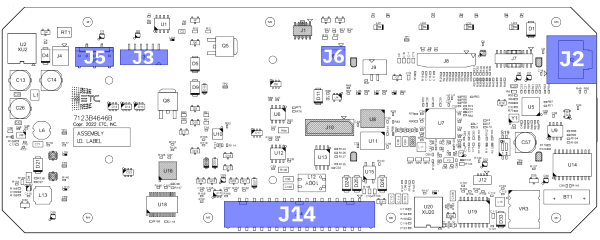 |
 |
 |
- Secure the mounting plate to the control enclosure using the original four screws.
- If necessary, reinstall the panel deadfront.
- Re-energize the panel.
Check Rack Class and Calibration
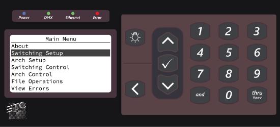
- Hold down the [1] key on the E-PCP and briefly press the recessed reset button using a sharp implement such as a pencil.
- Continue holding down [1] until the panel boots into the Manufacturing Test menu.
- Scroll down to [Rack Class Test] and press [✓].
- The rack class listed should match the panel type; "ERP" for ERP Mains Fed, "ERP-FT" for ERP Feed Through, and "Sensor IQ" for Sensor IQ.
- If a different rack class is listed, use the up and down keys to select the correct type.
- Once the listed rack class matches the panel type, press [✓]. Nothing will happen at first; wait up to 30 seconds for the test to run.
- The Manufacturing Test menu should now display [Rack Class Test Pass].
- If you instead see [Rack Class Test Fail], try the previous steps again; if the test fails a second time, contact ETC Technical Services.
- ERP Mains Fed and Sensor IQ only: Scroll down to [Calibration] and press [✓].
- The value listed should match the input voltage multiplied by 100; 12000 for 120V panels or 27700 for 277V panels.
- If the value does not match, adjust it using the up and down keys.
- Once the value matches the input voltage * 100, press [✓].
- Press [<] to exit the Manufacturing Test menu.
Loading a Saved Configuration
If you saved your configuration to USB before installing the loaner, or if you have a backup of the configuration, you can now load that configuration to the loaner E-PCP. If you do not have a backup of the configuration to load, skip this step.
Quick Rack Setup
If you cannot load a configuration from the backplane or via USB, you will need to perform a quick rack setup to write a new configuration from scratch.
Press [✓], then navigate to [Switching Setup] > [Quick Rack Setup].
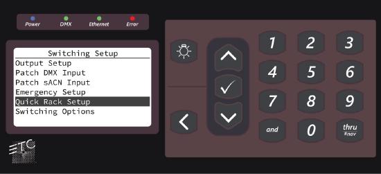
Assign the output count, DMX and/or sACN start address, and Echo space according to your system, then select [Apply All].
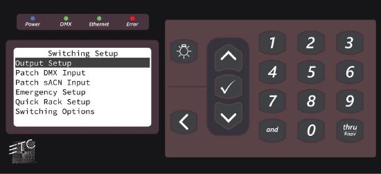
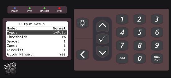
Advanced Rack Setup
Your rack may require advanced configuration if it contains multiple relay types or a custom DMX/sACN patch.
To configure multiple relay types, select [Output Setup] in the Switching Setup menu, then select the circuit you wish to modify. Change the type to match the relay installed in that slot; options are 1 Pole, 2 Pole and 3 Pole. Dimmer is available only on ERP Mains Fed for panels with 300W dimmers installed in place of relays.
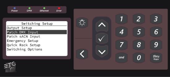
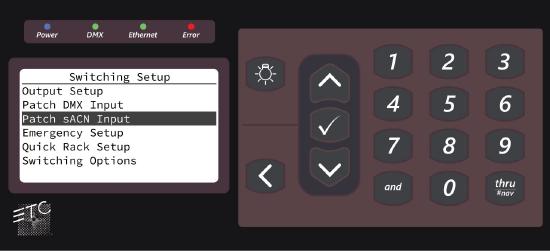
To configure custom DMX or sACN patch, select either [Patch DMX Input] or [Patch sACN Input] in the Switching Setup menu. The next screen will allow you to define a custom DMX or sACN address for each relay individually.
Other Situations
If you have a situation not described above, or you need help following these steps, please contact ETC Technical Services.