Sensor IQ Smartbreaker Pin Out
Explanation
The Sensor IQ Smartbreakers have 9 pins on the bottom that connect to the data communication bus within the rack. These pins can be useful in determining if a breaker is malfunctioning or if an issue is originating elsewhere. Please see the image and the explanations below.
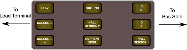
Contacts function as follows:
- +3.3V: provides DC power for the LED and internal electronics
- Solenoid (-): The negative pole of the solenoid. (See Section Below)
- Solenoid (+): The positive pole of the solenoid. (See Section Below)
- Ground: Ground connection for the circuit.
- Hall Sensor 1: Output from the first Hall Effect Sensor.
- Hall Sensor 2: Output from the second Hall Effect Sensor.
- Current XFMR: Measure the current flowing through the load.
- ID1 and ID2: Pins for identifying 1-, 2-, and 3-pole breakers. (See Chart Below)
ID Pins
The ID pins tell the Sensor IQ Processor the Breaker type. Pins are either connected (resistance <1Ω) or open (resistance >30kΩ).
| Breaker Type | ID1-Ground | ID2-Ground |
| No Breaker Connected | Open | Open |
| 1-Pole | Open | Connected |
| 2-Pole | Connected | Open |
| 3-Pole | Connected | Connected |
Solenoid
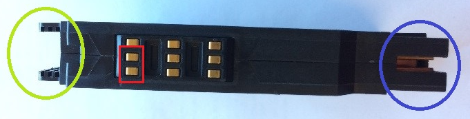
The solenoid is a coil which can potentially fail in two ways, either by shorting or by going to an open circuit.
Measure the solenoid coil in resistance mode between the (+) and (-) (bounded by a red box in the photo)
- A good coil should measure around 20-24Ω.
- A shorted coil will measure 0-1Ω.
- An open coil would measure as an open circuit.
NOTE: There is some natural variance in the product for the "good coil" measurements. It is possible to see readings of 15-19Ω. This is also an acceptable reading.