Understanding Power and Control Paths for Sensor IQ
This article provides a description of the paths taken by both power and control circuitry through the panel in an effort to assist with understanding of the product.
The information in this post is provided to assist in troubleshooting. Perform work at your own risk. ENSURE ANY POWER FROM DEVICES HAS BEEN DISCONNECTED BEFORE SERVICING ANY EQUIPMENT. If you do not feel comfortable performing the work, please contact us or your local service center. Be aware that ETC and its Affiliates are not responsible for any damage or injury caused by service of our products by anyone other than us or our authorized service providers, and such damage is excluded from the product’s warranty.
Power Path
NOTE: The Sensor IQ (SIQ) panel can be installed with the power feed at the top or bottom. For the purposes of this article, assume the panel to be installed with the power feed at the top of the panel.
AC Feed Wire
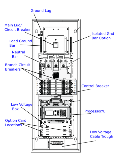
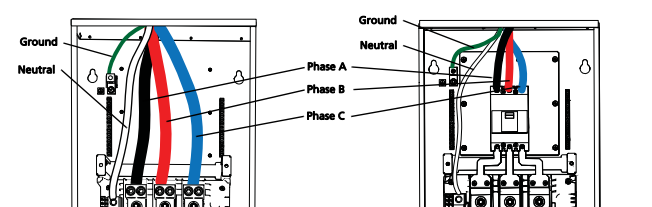
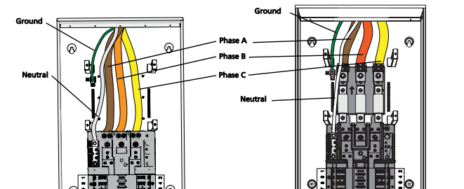
The Sensor IQ (SIQ) Panel is a mains feed type of panel. It is fed with either 3-phase power or single-phase power (single-phase still has two (2) phases) depending on the type of panel being installed. The SIQ panel has an option to install a Main Circuit Breaker into the top of the panel to separate the panel from this incoming power. If a Main Circuit Breaker is not installed in the panel, then this breaker is provided by others and will be in the circuit someone before the rack itself.
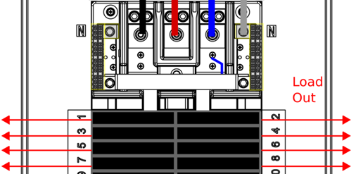
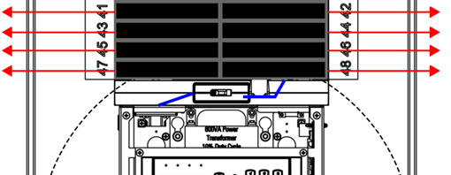
The main power feed lands on 3 phase bars: Phase A, Phase B, and Phase C (2 bars for single phase: Phase A and Phase B). These phases then go on to feed power down the center of the panel where the branch breakers connect to the phase bussing to receive power. The phases alternate with each row of breakers: circuit breakers 1 and 2 are Phase A, 3 and 4 are Phase B, 5 and 6 are Phase C, and so on, looping back to Phase A for circuit breakers 7 and 8. (Single Phase panels alternate Phases A and B accordingly.) Once the power enters the breaker, if the breaker is in the 'closed' (on) position, the power flows through the breaker and onto the wire going to the load at the other end of the wire.
Neutral and Ground
| The neutral and ground feeds for incoming power also have their own termination points in the top of the panel. The ground feed terminates directly to the ground terminal block and the neutral feed terminates directly to the Neutral terminal block. These locations can be used to terminate the neutral and ground wires from the loads, whereas the AC line from the loads terminates to the breakers. |
120v
277v
|
Power to Control Circuitry
| The relay control circuitry must also receive power from the mains feed. This power comes from Phase C. There is a black wire connected to the Phase C buss bar with a ring crimp that runs down the length of the panel along the even breaker side of the panel to the blue control breaker just below the last row of branch breakers. The neutral for this breaker follows a similar path from the neutral buss bar down the odd breaker side to the control breaker housing. The power then flows into the Low Voltage Box through the white connector in the top-left corner to connect to the Control I/O card and the transformer. |
|
Control Path
AC Voltage
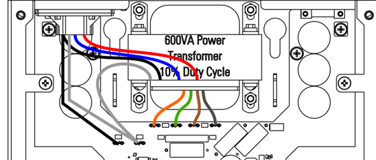
Inside the Low Voltage Box, the AC voltage wires split off into multiple wires. The black wire going to the "Y" shaped Control I/O card terminates to a spade connector on the left hand side of the card, along with a white neutral wire. Other AC wires run directly into the transformer at the center of the Low Voltage Box. Here the voltage is stepped down to appropriate levels, output from the transformer and terminated to spade connectors on the Control I/O card with 4 colored wires just below the transformer itself.
DC Voltage
|
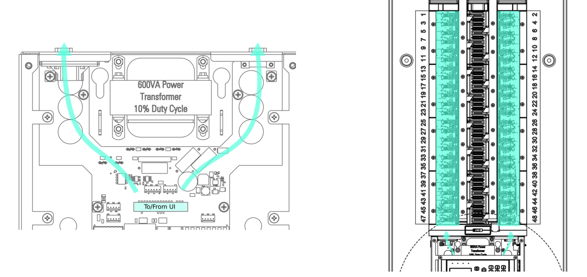
From here the voltage is converted to DC voltage in various voltages as needed and distributed throughout the Control I/O card. The primary voltage used here is 24v DC. 24v DC flows to the Echo Power Control Processor(E-PCP) to power it, as well as to any connected option cards: 0-10v Option cards, Network Option cards, Contact Input cards, and DALI Option cards. Communication to/from these option cards flows along the same multi-wire harnesses that provide the voltage to them. This data is combined with any other incoming data to the Control I/O card, such as DMX, sACN, or Panic. This information is gathered and passed to the E-PCP for interpretation along the gray ribbon cable at the center of the Control I/O card. Once interpreted, the commands from the E-PCP flow back down the ribbon cable and make their way up to the left (odd) and right (even) wings of the card and to the breakers via the Signal Distribution (Signal Distro) cards. These Signal Distro cards lie underneath the breakers (but above the black and white wired to the Control breaker housing) and communicate with the breakers by way of a 9-pin connection to each of them. This same path carries data about the breakers, such as breaker status and type back to the E-PCP to display on the LCD screen. |
|

Troubleshooting
If you are having issues with your Sensor IQ product, please contact ETC Technical Services or your ETC certified Dealer.