Understanding Mosaic Constant Voltage and Current Modules
The Hardware
There are two styles of Mosaic LED drivers, the Constant Current and the Constant Voltage. Both a Constant Current driver and a Constant Voltage driver can be used power LEDs, however, each style of driver delivers power in a different way.
There are three variants of the Mosaic Constant Current module; 350 mA, 500 mA, and 700 mA
There is one variant of the Mosaic Constant Voltage module which allows for up to 40w per channel for a total of 180w per driver.
Each constant current driver is 6 channels and supports 8-bit DMX control.
Each constant voltage driver supports both 8-bit and 16-bit DMX control. This DMX dimming mode can be selected via RDM.
Current vs Voltage
Current is measurement of electrons passing a single point in one second.
Voltage is the electrical potential difference between two points.
A Constant Current driver delivers a regulated current while varying the voltage along a circuit, this allows for a consistent current for each load. If an LED load is given an unregulated current, the load will burn brighter, but this will eventually lead to a thermal runway reducing lifespan of the LED.In short if an LED load is given too much current, the LED will get very bright and then fail. This is why it is critically important to know the required current for the LED load before connecting it.
A Constant Voltage driver delivers a consistent DC output voltage regardless of the current requirements of the connected load.
It is important to confirm the type of voltage or current required for the fixture or LED prior to connecting the Mosaic driver.
All Mosaic LED drivers are polarity dependent, incorrect polarity can cause damage to the LED fixture or driver.
Address and Testing
Each LED driver requires six sequential DMX addresses. A driver's address can be set via the front wheel or via RDM.
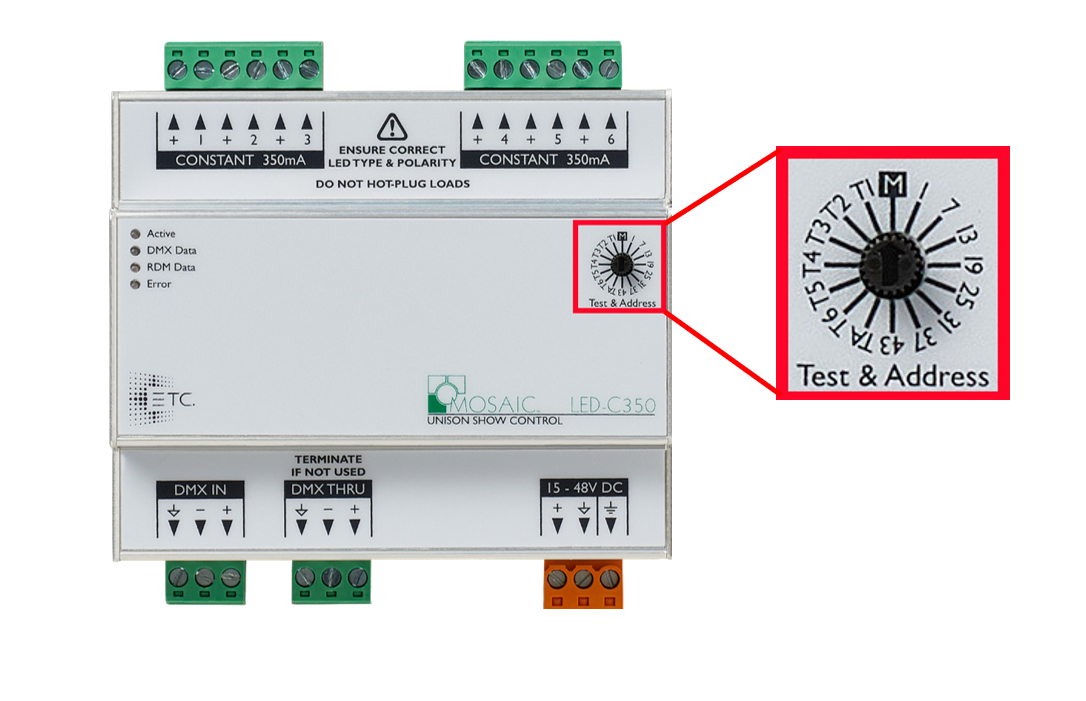
Setting the front dial to "M" , or managed, allows the unit to take an address via RDM. An RDM address can be applied via the patch tab in Mosaic Designer.
Setting the dial to 1 would set the units DMX address to 1 and each subsequent output on the driver would increment by 1 with last output being DMX address 6.Setting the front dial to "T#" will drive the output to 25 % , even if DMX isn't present, selecting "TA" will drive all outputs to 25%.
When placed in test mode, all incoming signals DMX signals will be ignored.
RDM Setup
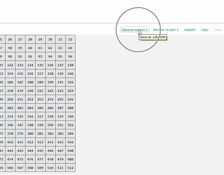
Mosaic LED drivers are non-networked controllers and thusly will not appear in the network of Mosaic Designer.
These devices will appear in the patch tab as RDM devices.
To change a driver's address via, navigate to the patch tab, select the controller and choose "Discover on port 1"
Devices that support 16-bit dimming will appear with personality that reads "CVD LED -16bit", select this mode if you wish use 16-bit dimming.
A 16-bit device will occupy 12 DMX addresses.
Power and Data
All variants of Mosaic LED drivers use the standard 12 to 48 VDC mosaic power supply.
A fully loaded a LED-x will consume 200 watts of power with all channels at full.
These drivers require DMX for non-local control, there is no option for direct network control on the drivers.
Data Input should be landed on the 3-pin header labeled "DMX In".
The outgoing data signal should be connected to the "DMX Thru" terminal.
If there are no further devices in the data chain the DMX Thru terminal must be terminated using a resistor.
Status LEDs
The front LEDs on the unit will indicate its status. All LEDs are red in color.
When power is applied to the driver, the ETC logo should illuminate and remain on until power is disconnected.
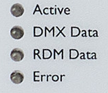
Active:Indicates that the unit is functional.
DMX data:Illuminates when DMX data is being received.
RDM data: Illuminates when RDM data is being transmitted.
Error: Flashes to indicate an error condition.