How to install a Gio/Ti keyboard retrofit kit
Warning: Please read these instructions completely before beginning work. If you feel this is beyond your skill level, contact an Authorized Service Center for assistance. ETC is not responsible for any damage that may occur due to improper installation.
Parts:
4240K1011 Gio Enhanced Cherry 94 Keyboard Kit
4350K1008 Ti Enhanced Cherry 94 Keyboard Kit
Purpose:
This document outlines the process to retrofit the facepanel keyboard to the newer version which uses Cherry MX switches. There has been some minor variance in the USB cables used internally, and the upgrade kit includes new compatible cables where applicable. These parts are backwards compatible with all versions of Eos Ti and Gio consoles.
Note: This keyboard can only be used with Eos Family software version 3.1.4 or higher.
If you are replacing a keyboard with a white circuit board, the new keyboard will not exactly match the old keys on the rest of the console. They will sit 1/16" deeper in the chassis, the text is not as white, and the clear, crescent keys are a bit clearer than the old ones. These are subtle differences that aren't a big deal to most, but if it is a concern to you, you may want to consider purchasing the 6x2 retrofit kit for Eos Ti or Gio.
Procedure:
- Power down the console.
- Unplug the console from mains power.
- Remove the back panel cover over the motherboard underneath the display panel.
- Lower the display panel completely.
- Open the face panel by turning the 2 locks on the bottom of the chassis using a flat head screwdriver or coin.
- Carefully disconnect the current facepanel keyboard from all its connections. Take note of where items are connected as they will be connected similarly on the new keyboard. Taking a photo is recommended.
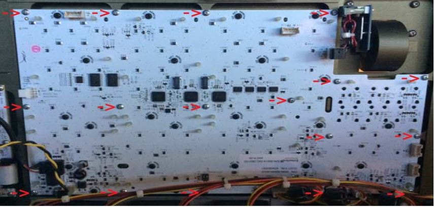
- To remove the facepanel keyboard, remove the indicated screws, do not remove any black screws labeled “DO NOT REMOVE”. BE SURE TO SAVE YOUR HARDWARE (namely screws). You will need the existing hardware to reinstall your new facepanel keyboard.
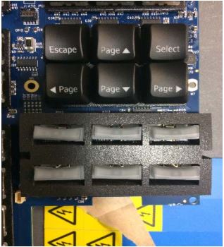
- Install the new facepanel keyboard using the same hardware from the original keyboard you removed along with the included, foam light blocker as shown below.
Note: Make sure the foam light blocker and keys are aligned appropriately to ease with installing the new facepanel Keyboard.
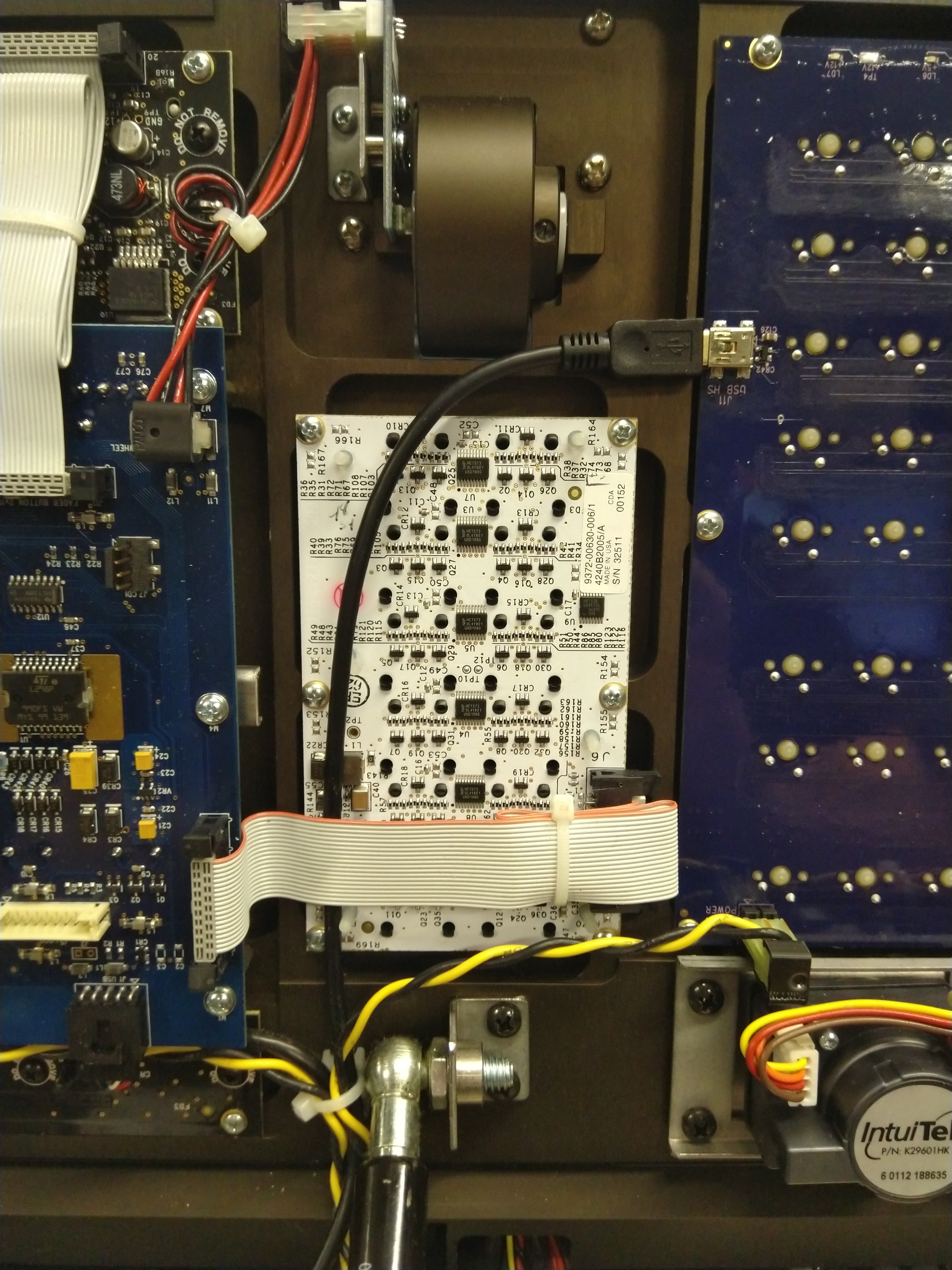
- If replacing a white keyboard, it will require the USB cable be replaced due to connector changes. If so, carefully trace the USB connection cable back to the motherboard of the console. Using cutters, carefully free the cable from the cable ties. Take note of the cable path as the new USB cable should be routed in a similar fashion.
- If the motherboard's USB connector is a 5pin header, make sure the red wire is on pin1 or towards the front of the console. Otherwise it will be a normal USB A connector common to all PCs, and it should connect as usual. When in doubt, check fitment prior to removal and connect exactly as the old one was.
- Route the new USB cable to the facepanel Keyboard using the provided cable ties to rebundle.
- Lower the console face panel, locking it closed.
- Re-Install the back panel cover.
Note: You may wish to test the keyboard functionality before re-installing all the screws. - Plug in mains power and turn the console on.
- Navigate to ECU->Settings->Maintenance and launch the Face Panel Test application to verify functionality.
- Press each button, rotate the level wheel and test each encoder to make sure connections are as expected. If all looks as expected your new facepanel keyboard is correctly installed.
Additional Information:
If you have any questions or issues with this process, please contact ETC Technical Services.