Wiring Multiple ALCR Emergency Input in Parallel
Symptoms/Issue
For some systems it may be desirable to have a single contact triggering multiple ALCRs. How should that be wired for the ALCR-PP and the ALCR-DIN units?
Description/Explanation of Issue
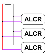
ETC’s ALCR (Automatic Load Control Relay) features a contact input connection which allows them to be switched from normal to Emergency mode using an external dry contact, for example a fire alarm. This is a supported configuration for up to 10 ALCRs. Polarity must be maintained as shown below

ALCR-PP (PowerPack style unit)
The ALCR-PP has a single loop of wire coming from the side. When wiring multiple ALCR units to a single contact, the ALCRs must be wired in parallel, and the polarity of the wiring must be maintained.
As the ALCR-PP has a single color wire loop, you will need to determine which side is the positive and which is the negative of the loop. In order to do this, you will need to perform the following test with power applied to at least the Emergency side of the ALCR:
1. Make sure all high voltage connections are secure and safe. Power up the ALCR.
2. Cut the purple wire loop for the emergency input, and strip the ends
3. Using a digital voltmeter set to DC volts, determine which lead is positive and which is negative. When the red probe is touching one wire, and the black is touching the other, and the reading on the voltmeter is not negative, you have identified the wires (Red probe = positive, black = negative)
4. Identify the wires (e.g. by applying colored electrical tape) as positive and negative
5. Repeat for the remaining ALCRs
6. Connect the wires to the ALCRs and switch, observing polarity
ALCR-DIN
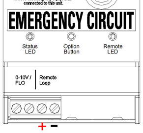
The ALCR-DIN has screw terminals for terminating the external loop. The positive and negative connections can be identified as shown below, allowing connection as shown in the diagram maintaining polarity.

Related Links/References
- Automatic Load Control Relay Downloads: Installation Guide
