Master Phase Loss Detector 2 Trouble Shooting
The information in this post is provided to assist in troubleshooting. Perform work at your own risk. ENSURE ANY POWER FROM DEVICES HAS BEEN DISCONNECTED BEFORE SERVICING ANY EQUIPMENT. If you do not feel comfortable performing the work, please contact us or your local service center. Be aware that ETC and its Affiliates are not responsible for any damage or injury caused by service of our products by anyone other than us or our authorized service providers, and such damage is excluded from the product’s warranty.
Explanation
The Master Phase Loss Detection 2 (MPLD2) is designed to send and receive many emergency signals to your ETC lighting system. It is like an Emergency Bypass Detection Kit (EDBK) but, instead of monitoring 3 Phase power with 2 inputs and 3 outputs, the MPLD2 monitors 3 Phase power with 15 card slots for inputs or outputs, or any combination to 16 Slots with at least 1 in and out. Each input card has 2 inputs. Each output card has 4 outputs. This gives a potential total of 2-30 inputs or 4-60 outputs. Of course this is an inverse relationship; the more inputs you have the less outputs you can have.

Standard Versions:
7180A1211 1in/1 out
7180A1212 1in/4 out
7180A1213 2in/8 out
7180A1214 4in/12 out
This can be triggered by several different situations, including a fire alarm, remote panic switches, or loss of Normal Power. Inputs are only Dry Normally Closed, Outputs are Dry Normally Closed.
WARNING: The steps below require the Interfaces to be powered on. This work should be carried out by a licensed electrician wearing proper PPE safety gear.
Trouble shooting
Normal Operation Input Loop fault
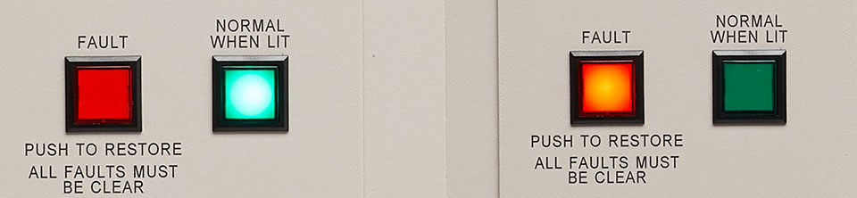
In normal operation the output relays are held closed by +24v. If there is a break in any of the input loops, the MPLD2 will move to the Fault State. Input faults are indicated on the Input cards by small Green LEDs. This is a latching fault; all input faults must be removed before you manually press the Fault button to restore.
The Normal when Lit it is indicator only, it is not a button.
If you have gone into fault and neither the Fault button nor Normal Indicator is lit, then you are in a power outage state. When power returns, it will come up with Fault button lit but no other input faults tripped. You will still need to manually press the Fault button to restore.
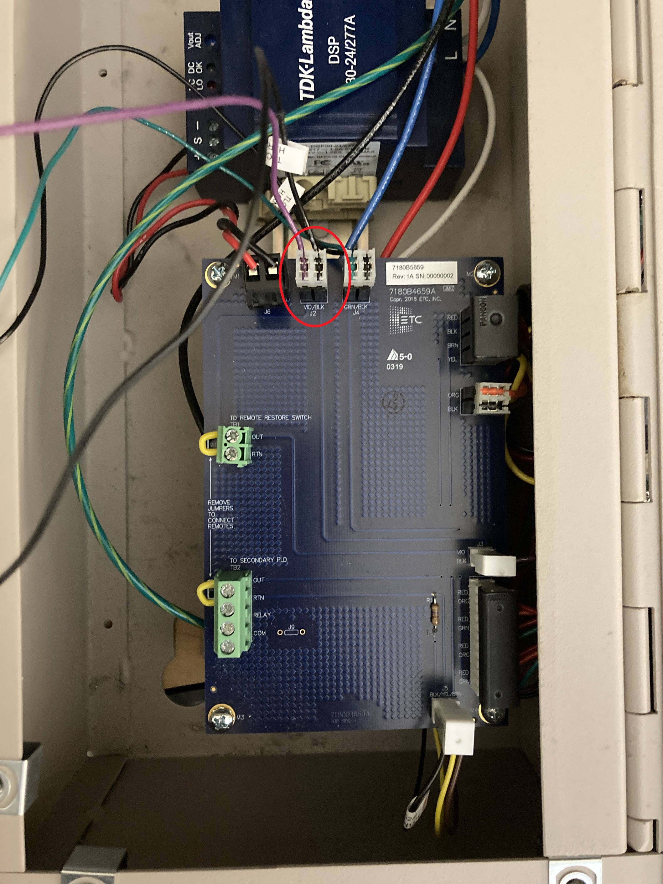
A lamp failure at the Fault button could cause the loop to fail. You can check if you have a failed switch/lamp by shorting the J2 pins on the Interconnect Assembly.
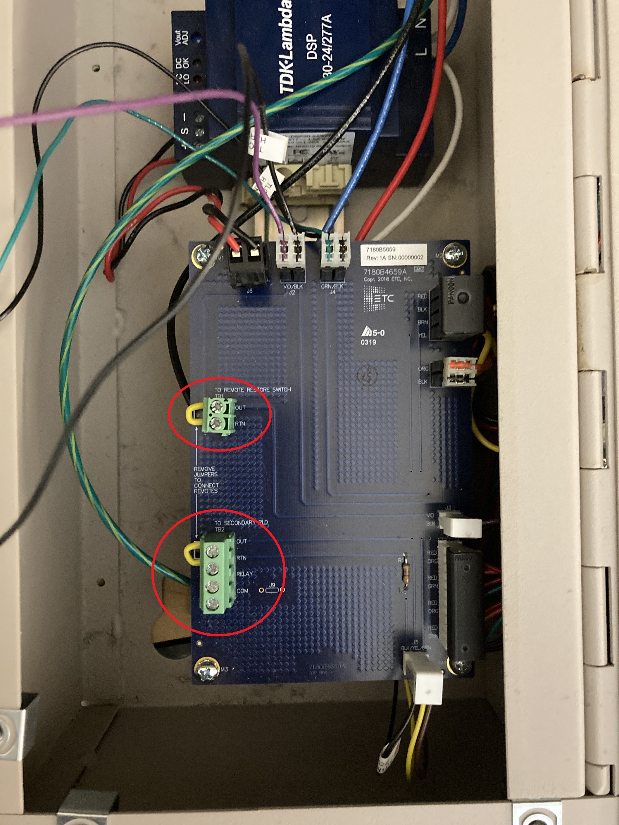
If you are not using a Remote Restore switch and/or secondary PLD, make sure the jumpers are still properly installed:
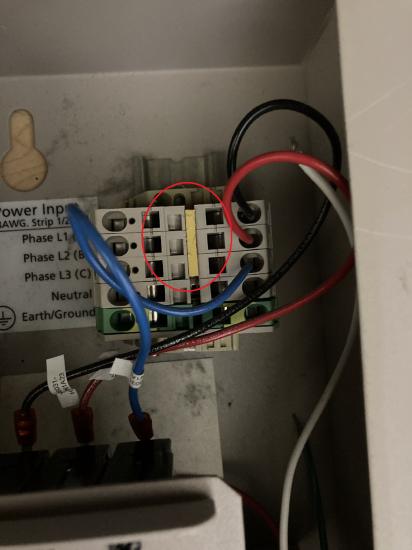
For Single Phase Operation:
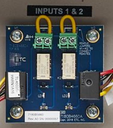
Make sure the Yellow jumper is installed in the input terminal block so that all the Bypass dector can fully operate.
For Dual Input Card:
1.Inputs land on top of card were the yellow Loop wire is connected. Inputs are Normal Closed only.
Wire pin out of input connect cable: Red = +24VDC, Black = Com, Brown = Input loop connection, Yellow = Input Loop Return
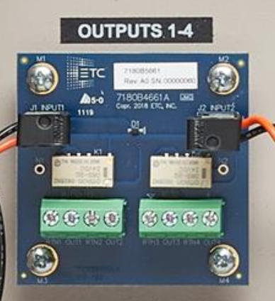
For Quad output card:
-
4 outputs land in pairs at bottom of card
Wire pin out of Input Connect cable: Red = +24VDC, Black = Com
Please contact your ETC dealer or ETC Technical Services for Part numbers.