DALI - Overview and Example Risers
Introduction
The information below is transposed from an ETC white paper downloadable from this link.
Summary
D.A.L.I. or Digital Addressable Lighting Interface is a control protocol used across a wide range of manufacturers of architectural lighting equipment. Like RDM, the DALI control protocol is a bi-directional data exchange allowing a controller to communicate with multiple devices at once, and those devices to communicate back to the controller. Unlike DMX, DALI is not a streaming protocol. Commands are sent only once from a DALI controller.
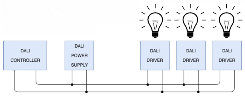
A DALI Loop has a single DALI controller, a DALI Bus Power Supply, and DALI drivers. A DALI loop supports up to 64 drivers. When more than 64 devices are needed, add additional loops to the installation.
DALI drivers must be configured as part of the system startup. DALI drivers contain the following information:
- Minimum Level
- Maximum level
- Power on level
- DALI bus power failure level
- Fade time
- Short address
- Scene-level information
- Group Membership
- Scene Levels
During configuration, each driver is addressed between 1 and 64. This is the short address, which allows discrete control of fixtures. This is similar to a DMX control system as each driver responds to a different address. Unlike DMX however, each driver must have a short address that cannot be shared by any other DALI driver on the same loop.
When compared to Ethernet and DMX protocols, DALI is considerably slower. While DALI drivers will change level when a command is received multiple drivers may not receive the same message at the same time or in any given order. Thus, lights may change intensity at different times. Because of this, a phenomena nicknamed “the popcorn effect” can occur during level changes. This is a drawback to the speed of the DALI protocol. For architectural installations where lights only change levels once or twice a day, this effect is less relevant. For live events, when the timing is critical, this effect is less desirable and very noticeable.
Control
DALI controllers send “Set Level” commands to individual drivers. Additionally, a command can tell a loop to “Go to Scene”. Each driver stores level information for up to 16 scenes. This is similar to how the ETC Echo Control System works in that level information is stored in the output device (not the central controller).
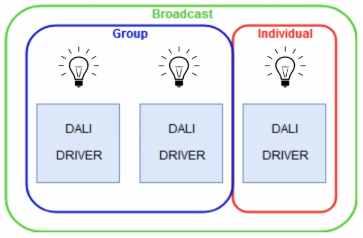
Control commands are summarized into three categories: Broadcast, Group, and Individual.
- Broadcast commands affect all drivers in a loop. Such as sending all of them to a level.
- Group commands affect only drivers that are a member of that group. Group membership is stored at the driver but configured using the DALI controller.
- A driver can belong to any combination of groups with a maximum of 16 groups available.
- Individual commands affect a specific driver using its short address.
By default, most DALI drivers have the “minimum power level” or the “power on level” set to full intensity. When initially energized, the fixture turns on. A common misconception is that the fixture is on, therefore "it has been configured”. This default property simply allows the fixture to be in use until a technician arrives to configure each driver. All drivers need configuration before they can be controlled.
Layout, Wiring, and Infrastructure
The infrastructure of a DALI system is similar to station wiring for a Paradigm system. Like Paradigm, DALI is topology-free and polarity-free. Two conductors are installed between components of the loop referred to as the “DALI Bus”. You can connect multiple drivers to the same wiring bus allowing multiple fixtures to be controlled by a pair of conductors. Unlike Paradigm, DALI bus wiring is also permitted to be installed in the same conduit as line voltage conductors (Class 1).
The length limitation per loop is 300 meters.
The power limitation per loop is 250mA.
A DALI Bus Power Supply is required for each DALI loop. This power supply should not be confused with off-the-shelf DC power supplies. It needs to specifically be a DALI bus power supply. A typical DALI power supply outputs approximately 16 VDC. When a DALI loop is energized, metering the loop shows a fluctuating voltage that is usually +/- 2-3 VDC from the power supply output rating. This fluctuation is how messages are sent between devices in a DALI loop. No fluctuation in voltage or no voltage is usually an indication of a communication or a wiring problem somewhere in the bus.
Example Risers and Comparison Chart
Attached below are Example Risers showing how ETC product are used with DALI.
DALI Example Risers, Rev 11_2019.pdf