DMX512 (aka DMX) Info
DMX512 (typically shortened to just DMX) is the most commonly used last-mile data protocol for theatrical control. DMX is an international ANSI standard maintained by ESTA available to use by any manufacturer. An enhancement to DMX512 called Remote Device Management (RDM) is also available in many ETC fixture and control products for remote configuration of devices. For a more technical overview of DMX see DMX512-A Standard on the ESTA website or the Wikipedia article on DMX.
Topology & Connectors
DMX systems consist of a single transmitting or 'source' device and between 1-32 receiving devices. For portable devices such as LED or automated fixtures, typically a receiver will use a five pin XLR type connector, with a male connector used for the DMX input to the device, and a female connector used for the DMX thru connector. Some devices also use a three pin XLR type connector, which can be adapted to or from a five pin when necessary.
DMX should always be daisy chained from device to device. It should never be "Y-Split" as this will reduce the reliability of communication.
DMX should be terminated at the end of the line with a 120Ω (Ohm) resistor between the data + and data - connections. Many ETC products feature ways to do this (for example, a Sensor+ rack has termination switches on the backplane PCB) without having to solder a resistor inline.
The most common wattage rating used for DMX terminating resistors it typically 1/4 watt or 1/2 watt. It is not important which is used.
For installed devices (such as Sensor3 racks), ETC has standardized on using an eight pin removable header, either as a screw connector type, clamp type, or a punchdown type connector depending on when the rack was shipped and installed. In 2019, we started using a three pin removable header with both screw connector type and clamp type options, and is expanding as the default option on many products.
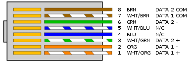
In some cases RJ45 connectors are used for DMX. ETC generally recommends only using RJ45 in patch panel type scenarios; most RJ45 connectors are not rugged enough to be used in the field for data connections. They are very sensitive to the ingress of dust, and are also mechanically weak. However, ETC does have some fixtures (such as S4WRD) which use RJ45 connections due to space constraints. ESTA has defined standard pinouts for DMX on five pin XLR and RJ45 connectors, both shown below. See DMX Over Category Cable for more detailed information about RJ45 terminations. ETC offers DMX terminations kits for use with either Belden 9729 (or equivalent) or Category type cable.

Cabling
ETC's recommend DMX cable, Belden 9729, consists of two twisted pairs plus a shield to carry data, which allows for a spare pair for 'out and back' type terminations if needed. Other cables may be acceptable, but must be specifically impedance matched for the digital DMX signal, meaning that microphone cable or other non-rated cable must not be used to carry DMX. ETC Applications Engineering can help with recommendations of other cables, but also maintains a publicly-accessible cable cross database which has a list of approved and unapproved cables for DMX and other signal types.
The original and 1990 versions of the DMX standard specify 120 ohm or 100 ohm 1 or 2-twisted pair shielded cable suitable for use with EIA-485 (120 ohm) and EIA-422 (100 ohm) electronics.
Ethernet Category cable (Cat5, 5e or 6) may also be used to carry DMX in an installation, however, special consideration must be given to shielding and termination. Previously ETC's guidance on solid core cable like Cat5 was that it should never be terminated into a screw down connector. This is still true for the original orange Weidmueller connector ETC formerly used, but the blue connector that replaced it has been certified for use with Cat5 cable.
Troubleshooting DMX
Since DMX is used in rough field conditions it is not unusual to have to troubleshoot problems with DMX control.
The basic troubleshooting steps are:
- Is the DMX terminated? Many people view the termination resistor as optional, and in some cases although DMX may work without it problems can be introduced by lack of termination. A small change to the DMX network, like adding another cable, may stop the system from working or cause intermittent effects like flicker of dimmers, twitching of moving lights and so on. Adding termination can help eliminate these effects.
- RDM's functionality is especially sensitive to a lack of termination.
- Is the cabling OK? DMX may continue to work partially even under extreme conditions like having one half of the data pair broken. If a fixture is misbehaving, connect it directly to the DMX source with a short jumper cable bypassing other DMX infrastructure. If it works normally then there is an issue with your cabling that should be investigated.
- Is the device OK? Damage to DMX transmitters or receivers can occur in many ways; lightning storms are a common problem. If the receiving device doesn't respond to DMX when connected directly to a known good DMX source via a known good cable, the device itself may need service to repair a damaged DMX input.
- Does the device support full speed DMX? The DMX512 standard allows a very wide range of timings for the parameters of the DMX signal. Some devices do not support the full range of timings. In order to help troubleshoot this, ETC products feature output speeds that can be altered to help slower devices. All current ETC transmitting products support DMX output speeds of Max (Default), Fast, Medium and Slow. If you have a DMX device that still misbehaves even when connected directly to a known good DMX output, try changing the DMX speed of the transmitter to see if the problem improves. Usually changing to slower speeds is best, but occasionally specific timings of fast or medium don't work so a faster speed could improve behavior as well. For further information on DMX speeds of specific ETC products see the DMX Speed article.
Advanced Troubleshooting:
- Are both ends of the cable grounded to the same ground reference? DMX is a differential signal with the common (pin 1) providing the reference for when the signal is high or low. Depending on the design of the DMX device, the common may reference Earth ground (through the power supply) or be an isolated ground reference. In some cases where one end of the DMX chain is referencing Earth ground while the other is isolated, the potential on the Earth ground can cause the reference point to float and can appear that there is no control or flickering control. In these instances, as a troubleshooting step, try lifting (disconnecting) common (pin 1) from one end of the DMX line. If this resolves the issue, an optical isolator is recommended to be placed in line to maintain proper DMX circuit design while correcting for the difference in potential on ground.
- Some systems use DMX optos or splitters between the transmitter and receiver. It is always possible a problem resides in this interim device, including but not limited to the device not having power, bad terminations on the input or output, or faulty DMX transceiver chips. If you're unsure whether a DMX splitter is a problem, temporarily bypass it allowing the source to directly transmit to a line of receivers. If the problem goes away then there is a problem with the splitter.