Capacitive Loads and Zero Crossing Blanking Time
We have had a history of not being able to control some types of odd loads with our dimming systems. Some fluorescent ballasts and electronic low-voltage transformers (ELVs) have a capacitive front end in their design in order to provide power factor correction and sometimes for power supply current during the off part of the half-cycle. The capacitor causes a shift in the current waveform so that voltage and current do not reach zero at the same time. Let's begin with a brief reminder of how SCR-based dimmers operate.
SCRs act as a switch that we can turn on whereas they turn themselves off under the correct conditions. They can be turned on anywhere during the power half-cycle as long as they have a suitable minimum load but can only be turned of when power is zero and there is no control signal to the gate. In Figure 1 we see a PWM firing signal approximately the width of the output AC waveform. In reality, with an appropriate load on the SCR, we only need to briefly pulse the SCR gate but as a rule, to verify that the SCR does not turn off early during diminishing loads, we keep the pulse high through a majority of the remainder of the half cycle. Remember that loads can diminish because they are smaller or because as voltage and current drops during the beginning and end of each half cycle, the holding current can fall away.
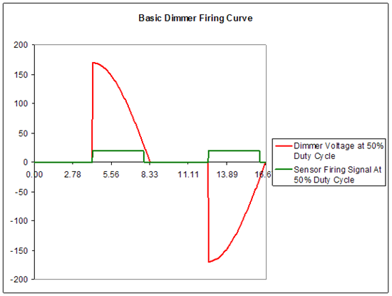
Figure 1
Since incandescent lamps are linear loads, only having a resistive component, we can easily get voltage and current to zero at the same time as we turn off the gate and the SCR turns itself off. Small loads and non-linear loads (capacitive or inductive) can create issues in dimming such as irregular turning off, flashing to off, or poor bottom end of the curve (small load or inductive) or false firing to full (capacitive). Today we will discuss capacitive loads. Proper management of power and the control signal is the key to being able to affectively dim non-linear loads.
When a capacitor is involved, current leads voltage as can be seen in the plots in Figure 2. This means that when the voltage waveform is rising from zero voltage, current is already present and the power cube can misfire to full as it has not ever lost its hold current. The trick, we have found, is to turn off the firing circuit to the cube in advance of the power shift to allow the cube time to turn off. This is part of what is called zero crossing blanking time.
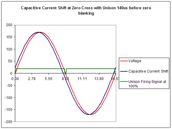
Figure 2
Zero cross blanking time, or zx time as it is sometimes referred to, is the amount of time before and after the point where voltage crosses zero in which we never send a firing signal to the power cube. Ideally most of this time is before zx as any blanking time after zx will mean that the dimmer can never go completely to its maximum possible output.
Figure 2 also shows the zx blanking in the Unison control signal which is approximately 140uS before zero and in total is between 200 and 240uS. Figure 3 shows this in detail also with the current non-zero at the time of blanking. In fact this is the problem. Current, voltage and control are never all at zero at the same point in time and causes a false firing condition.
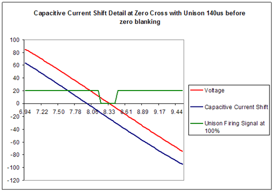
Figure 3
By increasing zx time we can then more readily dim a wider variety of odd loads. Fluorescent ballasts have a PF of near 1 when they are at full but when dimmed can reach much lower. In fact, it is the dimming of the Advance Mark X VEZ-1T42-M2-LD in which we find the problem with Unison dimming. This ballasts dim range is 130-277Vrms but when we get in the 165Vrms range we start seeing flashing to full. This is when we know that the dimmer is false firing from one half cycle into the next due to excessive capacitive current.
In Sensor+ v2.1.7 and SmartPack v2.0.4 we have changed the default zx time from 250uS to 500uS in an effort to more readily control odd loads. Figures 4 and 5 show the increased amount of blanking time at zero crossing. Note that there does exist a time where voltage, current and firing signal are all at zero. This capacitive shift only shows a PF of about 0.99 but in real applications the shift can be larger as SCR conduction does drop out before power reaches zero.
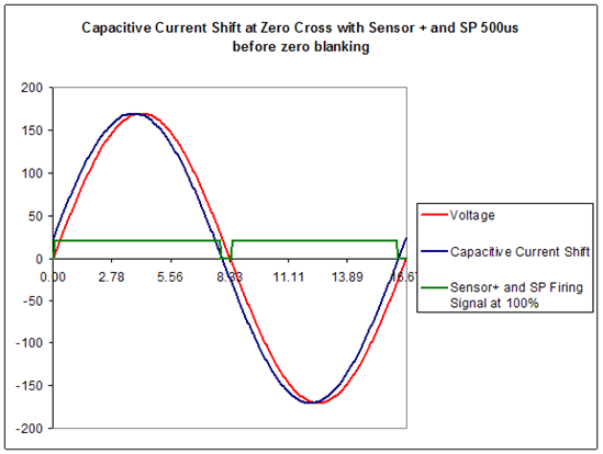
Figure 4

Figure 5
To assist technicians we have put in a provision in Sensor+, Sensor3, drd and SmartPack to edit the zx blanking time on a rack basis by using the service menus. In the case of CEM+ the zx time is saved as a rack parameter in the configuration file so that if control modules are changed the information can be transferred without re-entering the value. The problem of flickering to full with ELVs can usually be cleared up by changing the zx time from 500 to 750.
For CEM+:
- Use the login password of 4116
- Enter the ETC Only menu
- Edit the SCR Off Time
- Range 0 to 10,000 default 500
- Exit the menu
For CEM3:
- From the home screen enter access code 04116
- Scroll down in the menu to Scr off time and hit enter
- change the values with the wheel or # pad and hit enter
- Range 300 to 10,000 default 500
- back to exit
For SmartPack:
- Turn the unit off
- Hold down the home (<<), left arrow (<) and enter (checkmark) buttons down while powering back up. After a few seconds you will see the Self Test Mode.
- Enter Dimmer Setup
- Edit the Set ZC Offtime
- Range 0 to 1000 default 500
- Turn off the SP and turn it back on the exit the menu
For Unison DRd:
- Enter Main Menu
- Enter Restricted Access
- Enter Login, type 4116 and press Enter
- After Logging in, the Main menu will have an "ETC Only" option at the bottom, choose this option.
- Adjust Blanking Time in the "ETC Only" menu.
- Range 300 to 10,000 default 500
- Exit the menu
The new Unison DRd dimming systems will employ the same zx timing and technology as we have introduced into Sensor+ and SmartPack. Solutions for architectural dimming systems in 120V and 277V are on their way and indeed work quite well. The Advance 277V ballast that has been our nemesis now works without issue. Also, a new dimmer module called the ELV will be the predominant ELV dimmer using a transistor based reverse phase dimmer and will be supported by both Unison and Sensor+.