Load Calculations - Behind the Numbers - Rigging
Overview
The Prodigy Load Calculator is intended to estimate the approximate load on each lift line and each powerhead/compression tube mounting beam in a Prodigy hoist system. The calculations are based off the total lifting capacity for each hoist model and take into account the fixed and dynamic components of the system. The fixed components of the system may include the powerhead, compression tube, compression tube beam clamps, loft block, and/or Prodigy Cable Management (PCM) components. The dynamic components are the load lifted by the hoist.
The beam clamp spacing, lift line spacing, and cable management information/spacing are used to determine the share of the load on each adjacent beam clamp. The Prodigy Load Calculator uses the position of each lift line relative to each adjacent beam clamp to determine the share of the dynamic load on each beam.
Sample Load Calculation
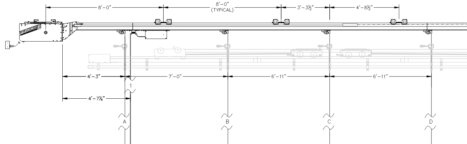
The sample elevation below has been simplified to show only the relevant dimensions used in generating a hoist load calculation. The ETC submittal drawing set (or provided customer drawings) is used by ETC to enter hoist and cable management information into ETC's proprietary load calculator.
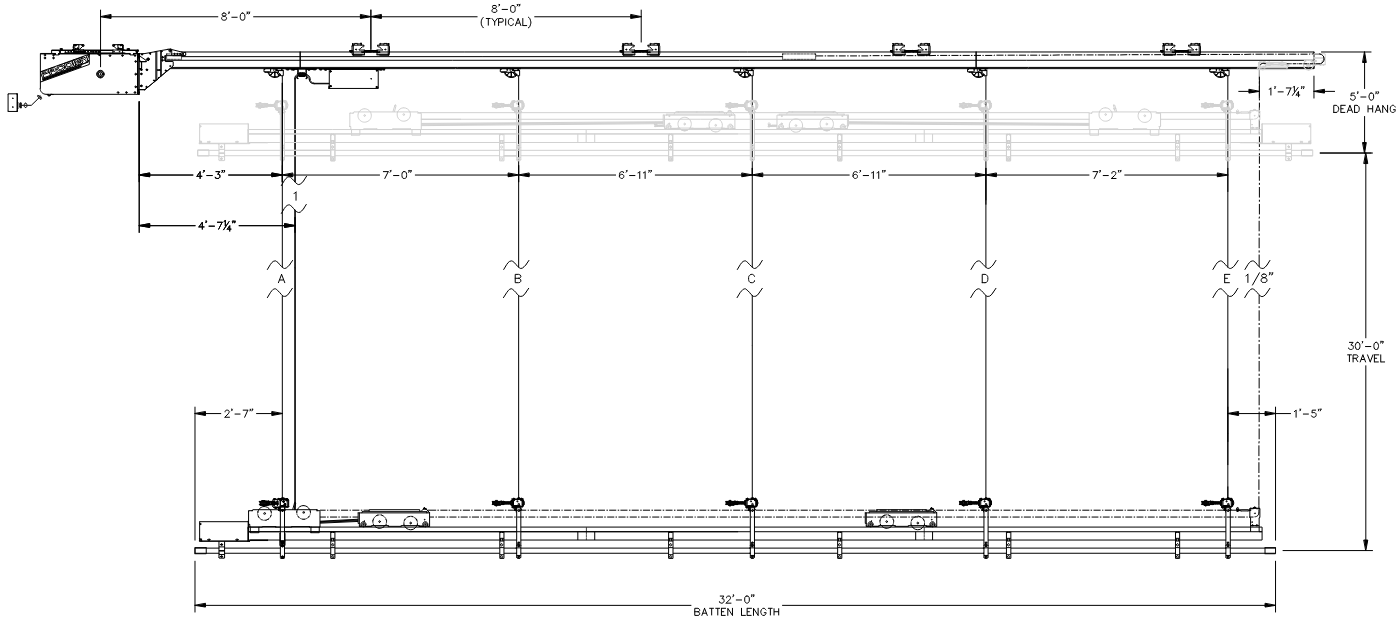
In this example the powerhead is primarily supported Beam 1 while the weight of the compression tube, Lift Line A, and the Flat Cable/Flat Cable Term Box, is shared proportionally between both the powerhead beam (Beam 1) and first compression tube beam (Beam 2). The calculator determines the individual beam loading from each system component before summing up the total load capacity on each beam.
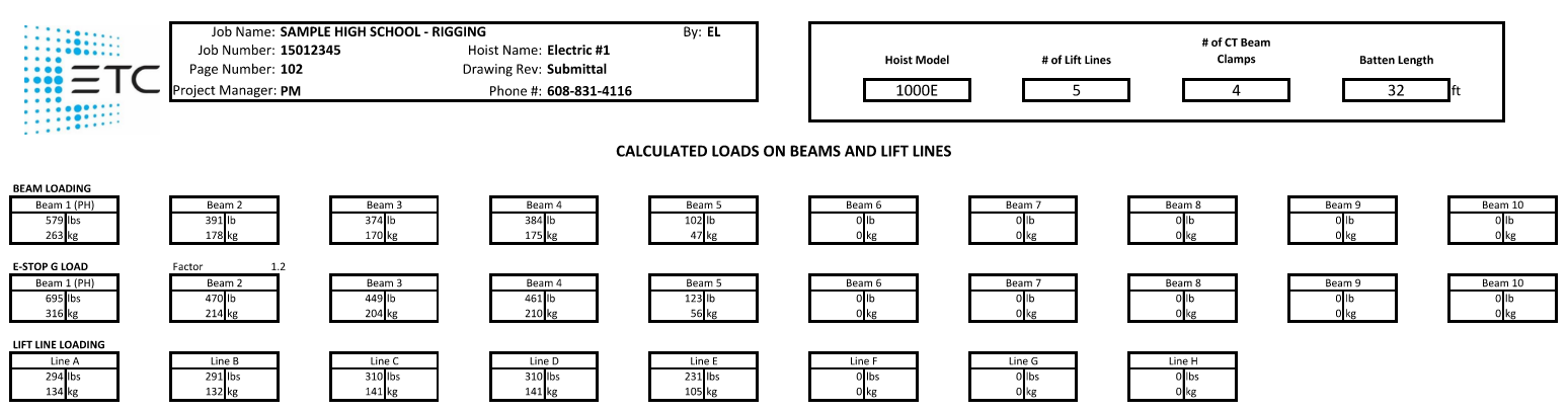
Looking at a simpler example the load between the second and third compression tube beam clamps (Beam 3 & Beam 4) will be shared as follows.
The weight of the compression tube evenly is shared between Beam 3 & Beam 4.
Compression Tube = 3.5 lb/ft @ 8'-0" = 28 lb
Beam 3 @ 16.5 lb
Beam 4 @ 11.5 lb
The load on Lift Line C is shared proportionally between Beam 3 and Beam 4; Beam 3 will take approximately 59% of the load while Beam 4 will take 41% of the load.
Lift Line C = 309.7 lb
Beam 3 @ 182.3 lb
Beam 4 @ 127.4 lb
Total Loading from system components between Beam 3 and Beam 4.
Beam 3 = 16.5 lb + 182.3 lb = 198.8 lb
Beam 4 = 11.5 lb + 127.4 lb = 138.9 lb
Note that the two totals above differ from the final values in the load calculator as both beams are taking half the compression tube weight of the compression tube between adjacent beams and a proportional share of any adjacent lift lines.
Notes
1.) The Hoist model number represents an estimation of the Working Load Limit (WLL) and not the total lifting capacity of the hoist. The load values provided are pertinent to the specific beam clamp and powerhead beam clamp attachment points, installed as indicated on the ETC drawings, on a per hoist basis and are calculated using the maximum lift capacity of the hoist plus the weight of the hoist components. Any changes in design or installation will alter the provided values and they will then need to be recalculated prior to installation. In all cases, it is recommended that a licensed structural engineer verify that the provided loads and intended hoist use are suitable for the designed building structure. This load calculator is only for use with Prodigy Hoists with Compression Tube. ETC is strictly a provider of the hoist load information and does not assume responsibility for building load verification.
2.) The load lifted by the Prodigy hoist with Compression Tube does not present any horizontal loading on the beams supporting the hoist when installed with ETC compression tube and slip fit beam clamps. Contact ETC for additional information.
3.) When calculating loads on each lift line the Prodigy Load Calculator assumes an evenly distributed load across the full batten length.
4.) ETC fixed speed hoists use a Category 0 Stop for end of movement/at a limit stop as well as when an E-stop button is pressed. There is not any ramping down of the hoist speed with a Category 0 Stop. ETC SoftLift and Variable Speed hoists use a variable frequency drive (VFD) to accelerate/decelerate the hoist at both the end of a move/at a limit and when an E-stop button is pressed, though a shorter ramp time of 0.2 - 0.3 seconds is used to bring the hoist to a stop during an E-stop event.
5.) The E-stop G Load value in the load calculator is the maximum load a hoist may see during an E-stop activation. Generally ETC hoists have a max G loading of 1.2 G during E-stop activation.