Understanding Power and Control Paths for Echo Relay Panel Mains Feed
- Last updated
-
-
Save as PDF
This article provides a description of the paths taken by both power and control circuitry through a mains-fed ERP.
 |
The information in this post is provided to assist in troubleshooting. Perform work at your own risk. ENSURE ANY POWER FROM DEVICES HAS BEEN DISCONNECTED BEFORE SERVICING ANY EQUIPMENT. If you do not feel comfortable performing the work, please contact us or your local service center. Be aware that ETC and its Affiliates are not responsible for any damage or injury caused by service of our products by anyone other than us or our authorized service providers, and such damage is excluded from the product’s warranty.
|
Power Path
 |
NOTE: The Echo Relay Panel (ERP) can be installed with the power feed at the top or bottom. For the purposes of this article, assume the panel to be installed with the power feed at the top of the panel.
|
AC Feed Wire
|
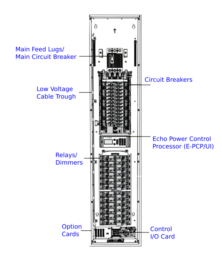
The Echo Relay Panel (ERP) is a mains feed type of panel. It is fed with either 3-phase power or single-phase power (2 hot + neutral + ground a.k.a "split-phase") depending on the type of panel being installed. An optional Main Circuit Breaker kit may be installed into the panel to separate the panel from this incoming power. If a Main Circuit Breaker is not installed in the panel, then an upstream disconnect device is provided by others and will be in the circuit somewhere before the rack itself.
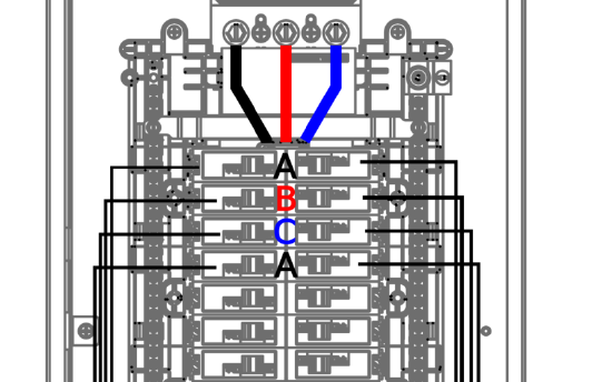
- Mains Feed power lands on 3 phase lugs connected to bus bars: Phase A, Phase B, and Phase C. (Single-phase panels have two bars: Phase A and Phase B)
- There is also an option to have a main circuit breaker installed for the Mains Feed power.
- These phases then feed power down the center of the panel where the branch breakers connect to the phase bussing to receive power.
- The phases alternate with each row of breakers: circuit breakers 1 and 2 are Phase A, 3 and 4 are Phase B, 5 and 6 are Phase C, and so on, looping back to Phase A for circuit breakers 7 and 8. (Single Phase panels alternate Phases A and B accordingly.)
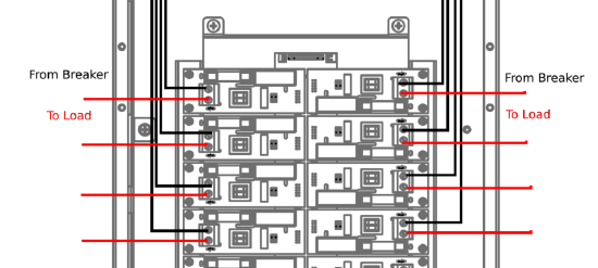
- Once the power enters s branch circuit breaker, if the breaker is in the 'closed' (on) position, the power flows through the breaker and onto the wire going to its respective relay/dimmer at the bottom of the panel. Power then flows through the relay/dimmer and out to the connected load.
|
|
Neutral and Ground
- The neutral and ground feeds for incoming power also have their own termination points in the top of the panel.
- The ground feed terminates directly to the ground terminal block and the neutral feed terminates directly to the Neutral terminal block.
- These locations can be used to terminate the neutral and ground wires from the loads.
- The neutral connection to the relays at the bottom of the panel consists of a single wire harness on each side of the panel that runs from the neutral terminal block to the top-most relay/dimmer, then it daisy-chains down that side of that panel, connecting to each relay/dimmer in line.
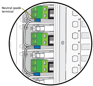
A neutral harness is connected to relay cards as shown above.
|
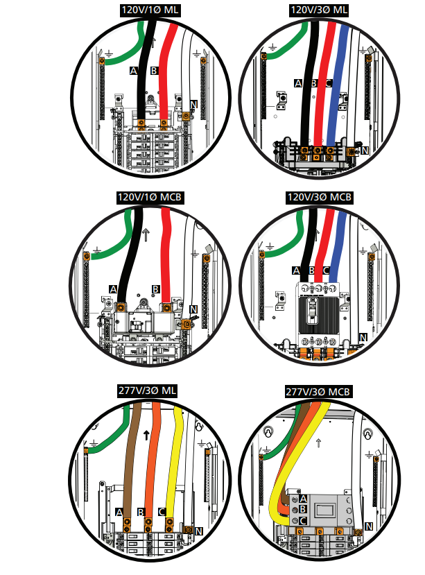
Mains power is terminated to an ERP in various configurations as shown above. |
Power to Control Circuitry
- The control circuitry that interprets how the relays should be controlled must also receive power from the mains feed.
- This power comes from Breaker 25, which is labeled Control.
- There is a black wire running from breaker 25 down to the center of the panel to the User Interface/processor (UI).
- The neutral and ground for the UI are run directly from the Neutral and Ground Terminal bars in the upper portion of the panels.
|
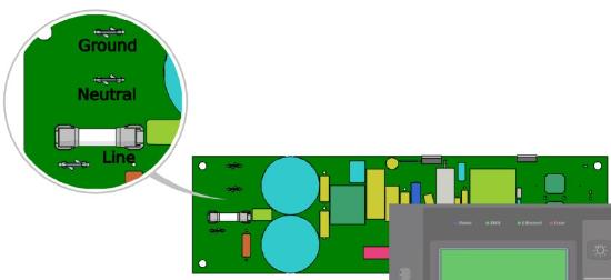
High voltage is landed on the power I/O card behind the UI to the terminals shown above.
|
Control Path
| |
- The power is converted to 24VDC on the Power I/O card behind the UI.
- 24VDC then flows to the to the UI (also referred to as the Echo Power Control Processor, or E-PCP) on a multi-colored 6 wire harness that powers the UI.
- There is also a multi-colored 5 wire harness from the Power I/O to the UI that delivers information about the incoming AC voltage for display on the screen.
- 24VDC also leaves the Power I/O card on a red/black 2 wire harness to provide power to the Signal Distribution (signal distro) card to provide it with power as well.
- Connected to the UI is a wide gray ribbon cable that carries 24VDC as well as communication data down behind the signal distro card to the Control I/O card at the bottom of the panel.
- This voltage and 2-way communication is used for DMX IN and THRU terminations, UL924 emergency termination, Echo Station communication, and option card communication.
- Option cards can include either a 0-10v card or a DALI option card on the left of the control I/O card, a contact input card to the right of the control I/O card, and a Net3/sACN option card set below the control I/O card. (PCP Mk2 has an integrated network interface and does not use the network option card.) One other option card, the Ride-thru option card, can also be installed to the back of the UI, and plugs directly into the UI with a red/black two wire harness.
- In the case that any of the low voltage signal wires pulled into the panel cannot be pulled into the bottom of the panel near the Control I/O card (signals such as network, DMX and Panic wiring as well as 0-10v or DALI, and contact input wiring) there is a low voltage barrier trough mounted to one side of the panel. this is removable with screws and can be placed on either side of the panel as needed.
Power IO card (behind the UI) control connections
|

Control connections on the I/O card behind the PCP |
|
Troubleshooting
If you are having issues with your ERP, please contact ETC Technical Services or your ETC certified Dealer.