How to Wire and Test Sensor IQ Transformer
Question
How can I test the outgoing voltage from the Sensor IQ Transformer that powers the control circuitry?
What connections do the wires go to? What is the correct order for the Sensor IQ Transformer wires?
Explanation
The transformer is located inside the low voltage box, behind the Echo Power Control Processor (E-PCP), also called the User Interface. It may be necessary to check the outgoing voltage if you have had to replace the transformer, or for troubleshooting purposes.
There are four wires coming out of the transformer that connect to the I/O card (the "Y" shaped input/output circuit board): Orange, Green, Brown, and Gray. All four of these wires are connected, but only two of them are actively in use. They are connected as follows (see picture below).
- Brown wire is connected to Normal Tap location - J12
- Green wire is connected to Return location - J8
- Orange wire is connected to placeholder location - J7
- Gray wire is connected to placeholder location - J15
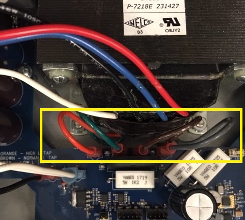
The Orange wire is call the High Tap and the Gray wire is called the Low Tap. These wires are present for dire situations only, where the incoming voltage to the panel may be too high or too low, and therefore are not actively being used. They are plugged into isolated points on the I/O card that serve as placeholders for the wires.
The Brown wire is the Normal Tap and the Green wire is the Return. These are the two wires that are actively being used by the panel. To get a voltage reading to prove the transformer is operating as intended, you simply need to meter for AC voltage between the Brown and Green wires. There is no need to unplug these wires for this test, as we have added test points to the I/O card for convenience (see picture below).
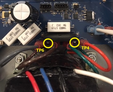
The Test points are labeled on the I/O card as TP4 and TP6. TP4 is located between the green and orange wires, but is a reference to the green Return wire. TP6 is located between the brown and gray wires, but is a reference to the brown Normal Tap wire. Simply meter between these two test points for AC voltage to confirm the transformer is operating correctly. Correct voltage is anywhere between 40-60VAC +/- 10%.
Fix/Solution
- Confirm wiring is connected properly
- Brown wire is connected to Normal Tap location - J12
- Green wire is connected to Return location - J8
- Orange wire is connected to placeholder location - J7
- Gray wire is connected to placeholder location - J15
- Turn on Control power breaker
- Meter for AC voltage between TP4 and TP6, looking for 40-60VAC +/- 10%