Unison CMEd Input DMX Driver Replacement
Explanation of Issue
![]()
- DMX driver chips may fail when subjected to excessively high voltage. This can be caused by a power event such as a lightning strike.
- You may need to replace the DMX driver chip if the CMd is not receiving DMX from a known working control device, or if the chip appears to be burnt or damaged.
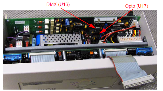
- If there has been damage, it is best practice to replace both the DMX driver chip (U16) and the DMX Opto chip (U17) on the dimming engine control card.
Dimmer racks without an accessible power disconnect device cannot be serviced safely. Before removing dimmer or control modules for service, de-energize main feed to dimmer rack and follow appropriate Lockout/Tagout procedures as described in NFPA Standard 70E. It is important to note that electrical equipment such as dimmer racks can present an arc flash safety hazard if improperly serviced. This is due to available large short circuit currents on the feeders of the equipment. Any work on energized equipment must comply with OSHA Electrical Safe Working Practices.
Solution
Before you begin
Setup a clean, well lit work area and take appropriate ESD (Electro-Static Discharge) precautions.
Tools Needed:
- #1 Jewelers Phillips Screwdriver
- Dual In-Line (DIL) Chip Puller
- DMX Input Transceiver Chip (LTC485) – ETC Part # Z1458-F
- (Optional) DMX Output Opto-Coupler Chip (6N137) – ETC Part # Z423-F
- Ensure power is turned off to the dimming rack.
- Open the door and locate the control module.
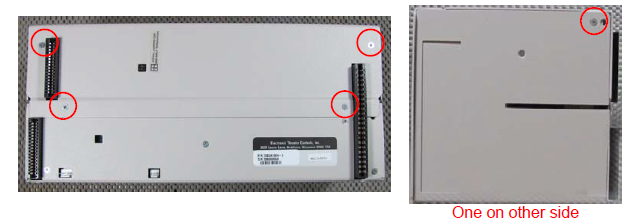
- Remove the CMd control processor from the Unison DR rack and place the unit on
a clean, stable surface. - With your #1 Jewelers Phillips screwdriver, remove the (4) circled screws on the
back of the unit and (2) along the short sides (noted below) and gently pull the cover
plate away from the processor.
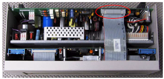
- Orient the processor so that the LCD display is facing you.
- Disconnect the circled ribbon connection.
- Locate the chips that need to be replaced.
- Gently remove the chips. In most cases, a chip puller will not be able to be
maneuvered into this space, remove the PCB Board or remove chip with your
fingers. - Insert the replacement chips into their sockets so that pin one is in the correct
location.
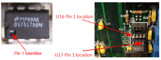
Note: U17 should be installed so that pin 1 is closest to the blue components. It is very common to install both U16 and U17 in the same direction when replacing the chips. If one or both of these chips are installed incorrectly, the processor will not receive DMX and will cause a 'No DMX' error
- Reconnect the wire harness, taking care that the red stripe faces the center of the
processor.
- Replace the lid and screws, making sure the ESD buffer strip on the upper portion of
the lid is inside the processor. - Restore the CMEd into the Unison DR rack. Press firmly on the unit to ensure it is
fully seated into its connections. - Close and lock the Unison DR rack door before restoring power.
If you have any questions regarding this procure, please contact ETC Technical Services.