My Material Doesn't Look Quite Right
Symptoms/Issue
Either using Augment3d's Materials Library or when importing my own material, it just doesn't look quite right... What can I do to try to understand and correct it?
This article presumes a base knowledge of UV and Normal maps. If you aren't familiar with those concepts, scroll down to read Understanding UV Maps and/or Understanding Normal Maps first before checking out the options in Augment3d.
Options in Augment3d
Augmented uses the Metal/Roughness workflow for Physically Based Rendering (PBR).
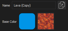
Stock Materials are read-only. To edit, duplicate the material then apply the duplicate to your model.
Base Color
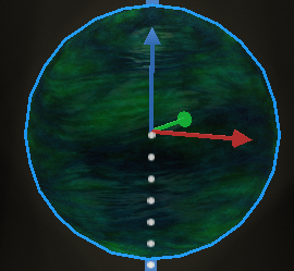
If the color of the object doesn't look quite right, you can adjust the base color in the materials editor. Remember that transparent areas in the texture image (the Alpha channel in an RGBA image) are affected by the base color. Using shades of grey can tone down an overly vibrant base color image while choosing a different hue can affect the material in substantially different ways.
Example:
| Base Color | Default | Adjusted |
|---|---|---|
| Material Display: | 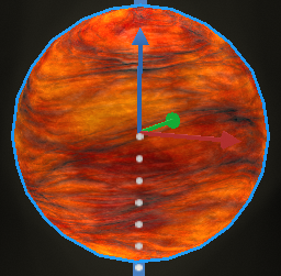 |
 |
| Augment3d Base Color Settings: | 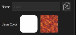 |
 |
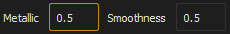
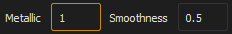
Metallic
Metallic controls how much light is reflected versus refracted off of the object in the material. In materials with normal maps, the normal map will affect the direction that the light reflects/refracts for certain areas of the material (see the depth of the grout in the example images). Objects that are poor conductors of electricity (dielectrics) tend to reflect a much smaller amount of light than those that are good conductors of electricity like pure metals.
Example:
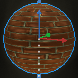
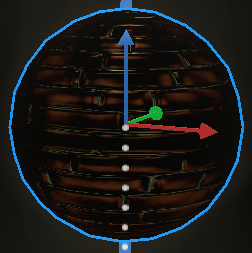
| Metalic | Default (0) | Adjusted to 0.5 | Adjusted to 1 |
|---|---|---|---|
| Material Display: | 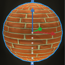 |
 |
 |
| Augment3d Metallic Settings: | 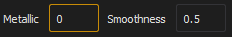 |
 |
 |
Augment3d does not attempt to show reflections of other objects in the scenes. Metallic/Smoothness affect only the light source reflecting off the surface
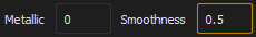
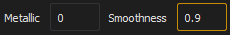
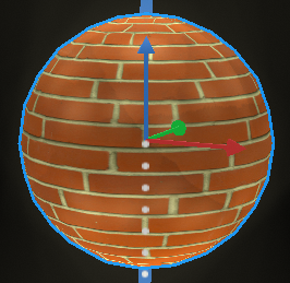
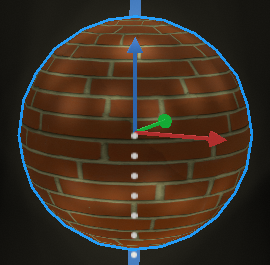
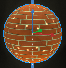
Smoothness
Augment3d calls the other half of the Metal/Roughness Workflow in Physically Based Rendering (PBR) smoothness rather than roughness. This controls how much the light is diffused as it hits the surface. Smooth (shiny) objects do not diffuse the light as much so the reflections are more concentrated, smaller points of light vs rougher objects that spread the light out further. If you are used to working with roughness values, invert the number (smoothness = 1.0 - Roughness).
Example:
| Smoothness | Adjusted to 0.1 | Default (0.5) | Adjusted to 0.9 |
|---|---|---|---|
| Material Display: | 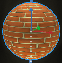 |
|
 |
| Augment3d Smoothness Settings: | 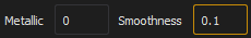 |
 |
 |
Augment3d does not attempt to show reflections of other objects in the scenes. Metallic/Smoothness affect only the light source reflecting off the surface
Rotation and Mirroring
Unlike other parts of Augment3d rotation of the material is always in the clockwise direction noted from 0 to 359 whole degrees. (Note: 360 = 0 and values greater than 360 are not allowed). Quick rotation buttons are offered for 90 degree clockwise and counterclockwise rotation by adding or subtracting 90 from the current value.
Additionally, mirroring the material left/right (about the vertical axis of the object) and/or top/bottom (about the horizontal axis of the object) is possible using the buttons provided.
Example:
| Rotation | Default (0) | Adjusted to 45 | Adjusted to 270 |
|---|---|---|---|
| Material Display: | |
 |
 |
| Augment3d Rotation Settings: |  |
 |
 |
| Mirroring | Default | Mirrored Left/Right | Mirrored Top/Bottom | Mirrored All |
|---|---|---|---|---|
| Material Display: | 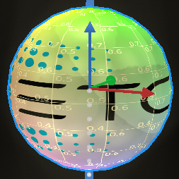 |
 |
 |
 |
| Augment3d Mirroring Settings: |  |
 |
 |
 |
Alignment
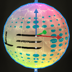
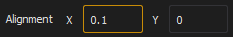
Augment3d aligns the material with the UV mapping of the object using the bottom left corner of the map as the 0,0 coordinate and the top right corner of the map as the 1,1 coordinate. Because the UV map wraps around the object, there is never a need to adjust with a value greater than 1 nor will the field allow for negative values as 0.9 is the equivalent of -0.1, and so on.
UV Maps are not always logical so it is not always easy to know how to adjust alignment to your needs. To aid in this process, ETC has provided a UV Map material in the Stock Library under Textures>Miscellaneous. To see how your edits will be applied, duplicate this texture and temporarily apply the material to your object. Note the current coordinates and how your adjustments are applied. Then apply your edits with the correct material assigned.
Example:
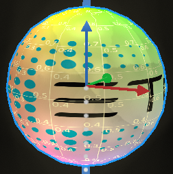
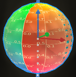
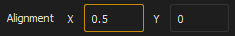
| Alignment X (Horizontal) | Default (0) | Adjusted to 0.1 | Adjusted to 0.5 |
|---|---|---|---|
| Material Display: | |
 |
 |
| Augment3d Alignment Settings: | 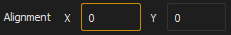 |
 |
 |
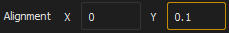
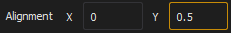
| Alignment Y (Vertical) | Default (0) | Adjusted to 0.1 | Adjusted to 0.5 |
|---|---|---|---|
| Material Display: | |
 |
 |
| Augment3d Alignment Settings: | 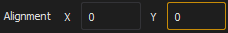 |
 |
 |
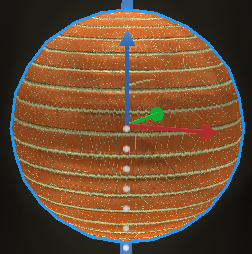
Repeat
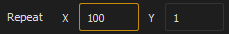
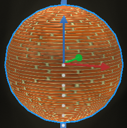
Textures are often designed to be small images that are repeated across the surface of an object. By controlling the number of times the material repeats, you can effectively control the scale of the material. Augment3d allows for control of both X and Y scaling via repeat with valid values from 0.01 to 100
Example:
| Repeat X (Horizontal) | Default (1) | Adjusted to 3.14 | Adjusted to 100 |
|---|---|---|---|
| Material Display: | |
 |
 |
| Augment3d Alignment Settings: | 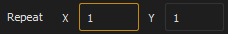 |
 |
 |
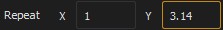
| Repeat Y (Vertical) | Default (1) | Adjusted to 3.14 | Adjusted to 100 |
|---|---|---|---|
| Material Display: | |
 |
 |
| Augment3d Alignment Settings: | 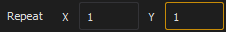 |
 |
 |
Understanding UV Maps
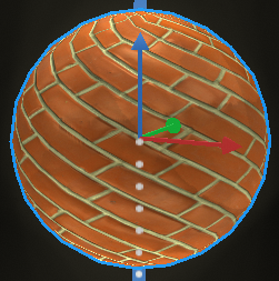
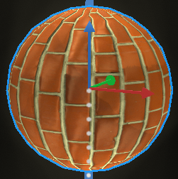
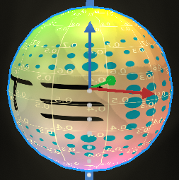
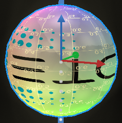
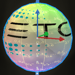
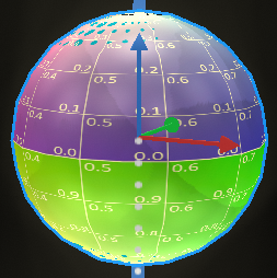
UV maps define where the vertices of the triangles that make up the 3D object appear on the 2D material. UV Maps are stored as a part of the 3D object and are not editable in Augment3d alone. To edit a UV map, use a 3D modeling tool, such as Blender to make changes and re-import your object in to Augment3d. Objects that have more than one face may have more than one UV map to allow the assignment of different materials to different faces. Sometimes the object has a single irregular surface (like a sphere) where it needs to be "unfolded" from the 3D into a 2D representation. Changing where those 3D vertices are mapped on the material will change how the object looks when the material is applied.
Example:
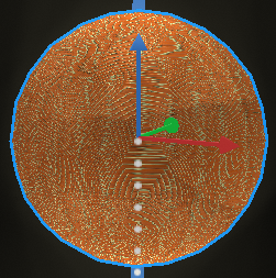
| Sphere UV Map Example | "Islands" | "Mercator-esque Projection" |
|---|---|---|
| Material Display: | 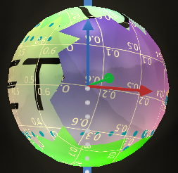 |
|
| Object Unwrapped onto UV Map Image: | 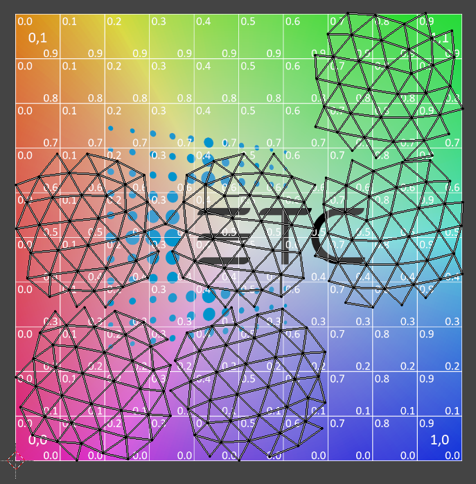 |
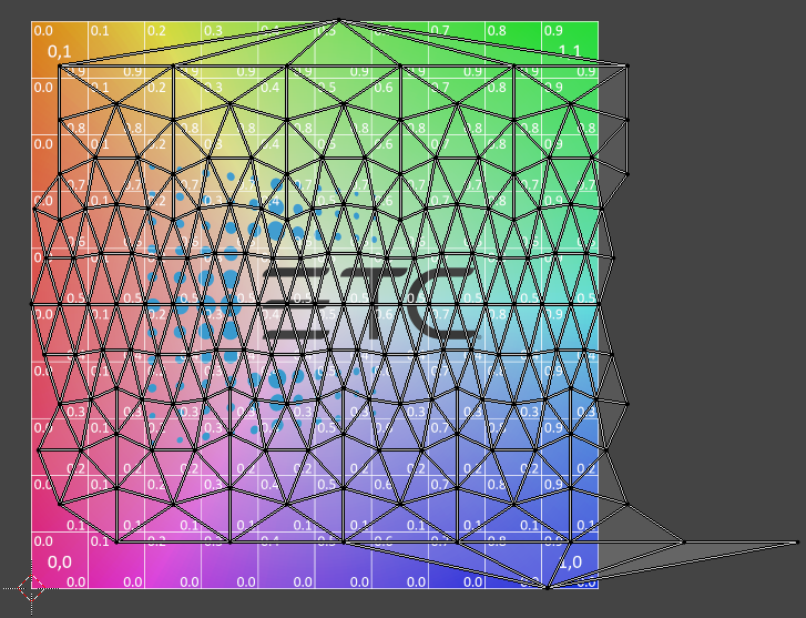 |
To see the UV Map coordinates on your 3D object, temporarily apply the UV Map texture from Stock>Textures>Miscellaneous
Understanding Normal Maps
Unlike most 3D modeled surfaces, surfaces in the real world are not usually flat and often have little bumps or details that stick out or dip inward from the face of the surface. When applying a 2D texture image to the flat 3D modeled surface, the lighting will not reflect the details of those non-planar surfaces and often fall flat or look unrealistic. Normal maps can be used to solve this problem by defining per-fragment normals instead of using the normals of the entire surface. Each per-fragment normal can then reflect or refract light individually adding greater detail.
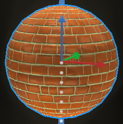
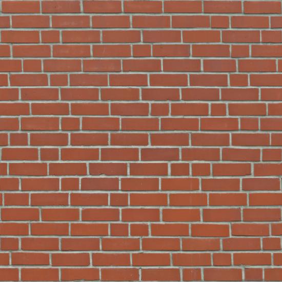
The normal map stores the per-fragment normal vector's x, y, and z components transformed into RGB values. Most normal maps have a blueish tint because most normals are closely pointing outwards towards positive z which is a blue-ish color. Normals which point towards positive y tend to be green-ish (like the top of the bricks in the example below) while normals that point towards positive x tend to be red-ish (like the sides of some of the bricks in the example below).
| Base Color Image (Texture) | Normal Map Image |
|---|---|
 |
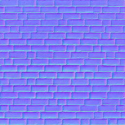 |
The normal map is scaled to the model's UV mapping coordinates and therefore is not required to be the same size as the base color image (texture).
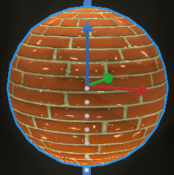
Example:
| Red Bricks | Without Normal Map | With Normal Map |
|---|---|---|
|
Default Metallic and Smoothness:
|
 |
|
|
Medium Metallic:
|
 |
|
|
High Smoothness:
|
 |
|
Editing Materials Externally
Often, a material is a texture image applied with the base color of the object (as described above). You can use your favorite graphics program to edit and create more complex materials. See How Do I Create a Custom Material for more details on creating your own custom material.
Imported materials not applied to objects are not saved in the show file. Apply your custom material to an object prior to exiting Augment3d to save your material into the show file.
Choose a Different Material
ETC has made available several hundred materials in the Material Packs available for download here. You may be able to find a material that works just right for your needs.