Opening a ColorSource Console for Repair or Troubleshooting Purposes
This article will describe how to open the ColorSource console to access various boards, wire harnesses, and test points inside the console
The information in this post is provided to assist in troubleshooting. Perform work at your own risk. ENSURE ANY POWER FROM DEVICES HAS BEEN DISCONNECTED BEFORE SERVICING ANY EQUIPMENT. If you do not feel comfortable performing the work, please contact us or your local service center. Be aware that ETC and its Affiliates are not responsible for any damage or injury caused by service of our products by anyone other than us or our authorized service providers, and such damage is excluded from the product’s warranty.
Before You Begin
Set up a clean, well-lit work area and take appropriate ESD (Electro-Static Discharge) precautions
Required Tools
- Philips #1 Screwdriver
- 3/8" nut driver
- Tweezers (may be required)
- Small containers for loose screws
Steps to Open Console
- Disconnect all cables and USB peripherals from the rear panel. Place the ColorSource console upside down on a flat surface
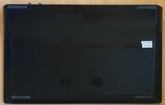
- Using the #1 Philips screwdriver, remove the screws of the flat bottom panel shown below. Remove the flat bottom panel and set aside
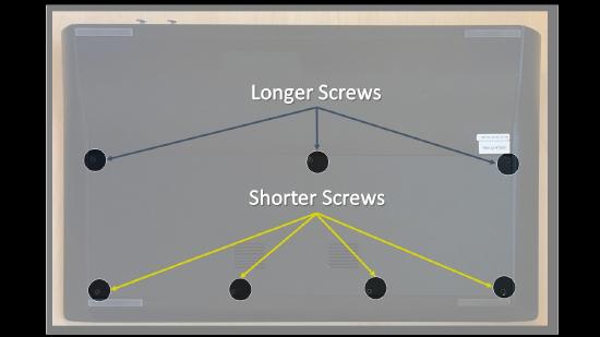
- 20-fader consoles will have (7) screws
- 40-fader consoles will have (8) screws
- Note that the screws in the middle of the console will have longer screws. Separate these screws from the shorter screws
- 20-fader consoles will have (3) long screws
- 40-fader consoles will have (4) long screws
- Remove the screws circled in YELLOW from the back panel (the side with the DMX port(s)). Remove the curved bottom panel and set aside

- 20-fader consoles will have (4) screws
- 40-fader consoles will have (5) screws
- If you need to remove the rear metal piece then remove the additional screws circled in RED. Use a 3/8" nut driver to remove the nut and washer circled in GREEN.

- 20-fader consoles will have 7 screws
- 40-fader consoles will have 8 screws
- AV consoles have an additional DMX port with two extra screws. CS40AV shown above.
- Perform any needed repairs/troubleshooting
Steps to Close Console
- Install the curved bottom panel and reinstall the back panel screws
- Install the flat bottom panel and reinstall all bottom screws
- Note that the longer screws should be reinstalled in the middle (3) or (4) screw holes. Installing these screws in any other place can damage the fader board or the control board
Parts
ETC Part Numbers
Short Screws: HWM1169
Long Screws: HWM2108