Installing Remote Macros in Express
The console provides four remote macro inputs through the 15-pin connector on the back panel labeled Remote Macro.
A user-supplied remote device connects to the console via a 24 AWG, aluminum-shielded, multi-conductor cable with one twisted pair designated for each switch (Belden 9507 S-R PCV Insulated or Alpha 5477 80 Deg. C 300 V PVC). The cable connector at the remote device will vary depending on the device itself.
| Console connector | Remote connector |
|---|---|
| DB-15 female | Connector type depends on unit |
| Pin | Function |
|---|---|
| 1 | +Macro 1,901 |
| 2 | –Macro 1,901 |
| 3 | +Macro 1,902 |
| 4 | –Macro 1,902 |
| 5 | +Macro 1,903 |
| 6 | –Macro 1,903 |
| 7 | +Macro 1,904 |
| 8 | –Macro 1,904 |
| 9 | Remote Trigger - normally closed (30V 1 amp max) |
| 10 | Remote Trigger - normally open (30V 1 amp max) |
| 11 | Remote Trigger - common (30V 1 amp max) |
| 12 | Ground |
| 13 | Ground |
| 14 | + 12 Vdc fused |
| 15 | + 12 Vdc fused |
Wiring remote macros
There are three typical ways to wire the Remote Go function:
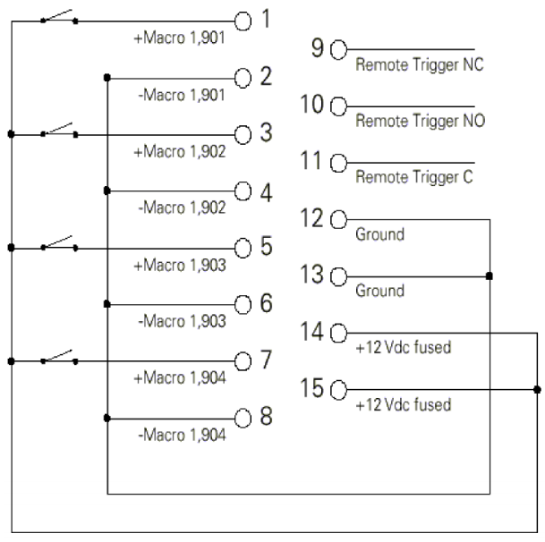
- Connect all -Macro pins (pins 2, 4, 6, and 8) to ground (pins 12 and 13) and switch the leads connecting the +Macro pins (pins 1, 3, 5, and 7) to +12 Vdc (pins 14 and 15) as shown in the following diagram.
- Connect all +Macro pins (pins 1, 3, 5, and 7) to the +12 Vdc pin (pins 14 and 15) and switch the leads connecting the -Macro pins (pins 2, 4, 6, and 8) to the ground (pins 12 and 13).
- Provide your own power supply that generates a 12 Vdc potential be- tween the +Macro and -Macro pins and switch either of these leads.