How do I connect an Emergency Bypass Detection Kit (EBDK) and a DMX Emergency Bypass Controller (DEBC)?
The information in this post is provided to assist in troubleshooting. Perform work at your own risk. ENSURE ANY POWER FROM DEVICES HAS BEEN DISCONNECTED BEFORE SERVICING ANY EQUIPMENT. If you do not feel comfortable performing the work, please contact us or your local service center. Be aware that ETC and its Affiliates are not responsible for any damage or injury caused by service of our products by anyone other than us or our authorized service providers, and such damage is excluded from the product’s warranty.
Background
- Emergency Bypass Detection Kit (EBDK)

- The EBDK is designed to sense the presence of normal power in a system, and provide a switched output (contact closure) in the event that normal power is lost. This switched output can be landed on any product that accepts an external panic trigger.
- Example: since most racks do not have built-in power-loss detection, you could use the EBDK to trigger a rack into Panic mode when normal power goes out.
- DMX Emergency Bypass Controller (DEBC)
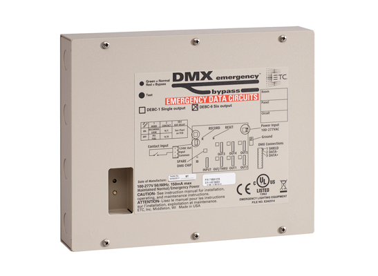
- The DEBC is designed to generate a DMX signal output on receiving a switched input.
- Example: if you have LED fixtures that need to turn on in an emergency, you could trigger the DEBC to send DMX to drive all the fixtures to full.
Explanation
The EBDK and the DEBC are designed to work as two separate products, and are often installed independently of one another, depending on the needs of each individual site.
Having said that, they are just as often installed together to work in tandem. Since the EBDK is unable to output DMX, and the DEBC is unable to detect loss of power, together they create a system that automatically generates a DMX signal on the detection of loss of normal power.
Answer
First, determine whether you want to connect your devices with a normally closed or normally open contact. Normally closed is the preferred option, but both are acceptable. Next, follow the instructions in the appropriate section below to wire your devices together.
Option 1: Normally Closed
- Configure your DEBC as Normally Closed by setting Dipswitch 2 to the ON position
- Run wire from the "Open in Emergency" (sometimes labeled "NC") and "Common" terminals of any of the three "Output" sections available on the EBDK.
- Land those wires on the "V out" and "In" terminals of the DEBC.
See below for an example of what this might look like

Option 2: Normally Open
- Configure your DEBC as Normally Open by setting Dipswitch 2 to the OFF position
- Run wire from the "Closed in Emergency" (sometimes labeled "NO") and "Common" terminals of any of the three "Output" sections available on the EBDK.
- Land those wires on the "V out" and "In" terminals of the DEBC.
See below for an example of what this might look like

Finish Installation
Once you're sure that you've correctly wired the two devices together, proceed with the rest of the installation steps for each device, as defined in the setup / installation guides (see Related Links). The EBDK, when it detects a loss of normal power, will now generate a closure that will trigger the DEBC into emergency (DMX bypass) mode to send a DMX signal out to the system.
Troubleshooting
When the EBDK is in Emergency mode, but the DEBC is not... please check the following:
- Ensure that your EBDK is wired to correctly monitor normal power
- Ensure that your DEBC is correctly wired for DMX output to whatever you are driving on in an emergency situation
- Continuity
- If your DEBC is configured as Normally Closed, confirm you see continuity between the EBDK output's "NC" and "Common" terminals when in Emergency mode.
- If your DEBC is configured as Normally Open, confirm you see continuity between the EBDK output's "NO" and "Common" terminals when in Emergency mode.
- Fire Alarm Jumper
- Ensure that the EBDK's Fire Alarm Output is configured correctly. If there is not a fire alarm wired to the EBDK, ensure the ETC supplied jumper is still installed between the fire alarm Input and V out terminals.
- Confirm that the dipswitches on your DEBC are in the correct positions. See charts below for reference.
Switch 1: Mode ON Panic look is recordable (snapshot) OFF Panic look sets all 512 channels to full Switch 2: Panic Input ON Normally Closed (NC) maintained panic input OFF Normally Open (NO) maintained panic input Switches 3 and 4: Panic Exit Delay Switch 3 Switch 4 Delay OFF OFF Deactivates panic look immediately when panic input is released. OFF ON Deactivates panic look 10 seconds after panic input is released. ON OFF Deactivates panic look 30 seconds after panic input is released. ON ON Deactivates panic look 10 minutes after panic input is released.
Related Links