Skip to main content
Navis RGBW fixture dis and reassembly
- Last updated
-
-
Save as PDF
Tools needed
- T10 Torx driver (a 2mm allen key will work as well, but may strip the head, use at own risk)
- A pick, preferably with a hook or angled end
- Small, flat screwdriver
- Small pair of needlenose pliers or similar for gentle grasping
Disassembly
- Remove the lens by pushing down on the lens with moderate pressure and twisting counterclockwise. If the lens will not budge, slip a small, flat screwdriver between the plastic tab and the housing as shown below. Alternatively, order part number 7496K1011 for an optic removal tool. Turn the fixture over and carefully drop the lens into your palm. Set it aside in a safe spot being careful to protect it with a towel, etc..
- Remove the 4 T10 Torx screws under the lense and remove the lens housing. Note the orientation of it in relation to the fixture, particularly with regards to the locating nub:
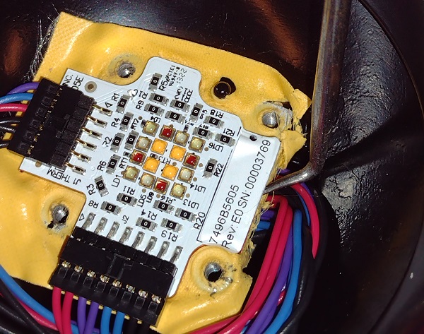
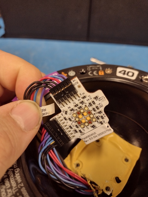
- Use a pick to pry up the array being careful not to damage the thermal pad underneath. Pull off the electrical connections, and hook one of them over the edge of the fixture so that they don't damage the thermal pad upon further disassembly.
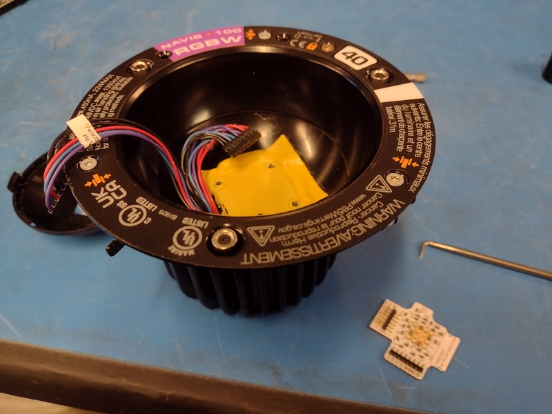
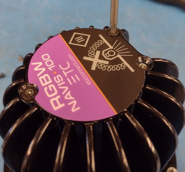
- Turn the fixture over and remove the 3 T10 Torx screws along with the back plate.
- While holding the array connections and wires from the other side, guide them through the hole while pulling out the control cards from the rear of the fixture. Pull the harness and PCBs out together as a whole, DO NOT try to disconnect them inside the fixture.
Reassembly
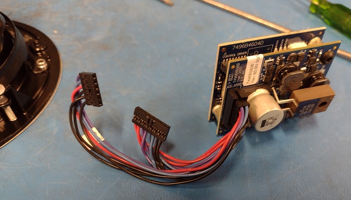
- Reconnect the harness as shown if removed:
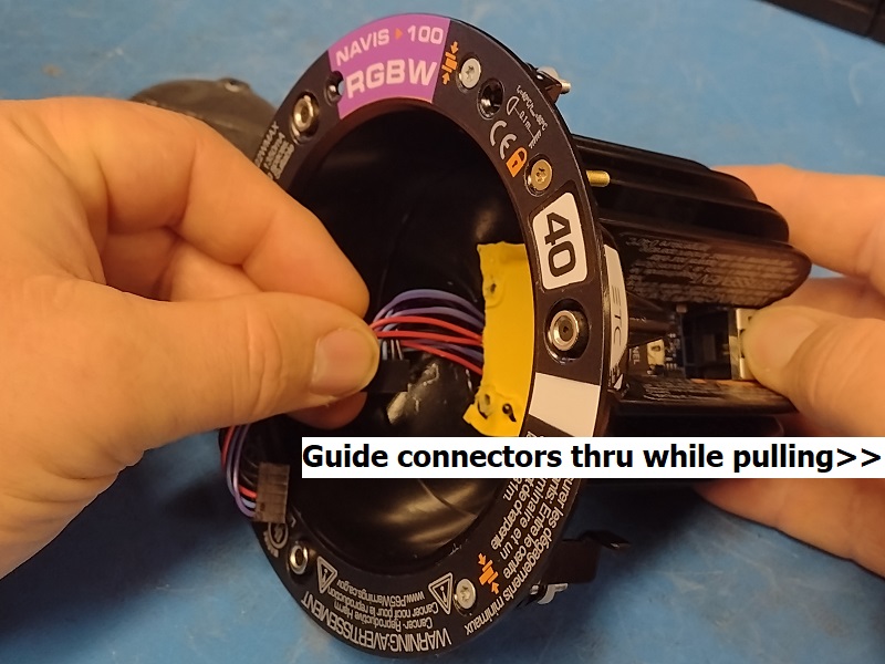
- Holding the control assembly above the fixture with the RJ45 jacks facing the same as the open slot in the fixture, guide the array connectors into the hole being very careful not to disturb the thermal pad. Try to press them against the back with your finger while pushing them through and sliding the control cards into the slot at the same time. DO NOT PUSH the control card into place yet.
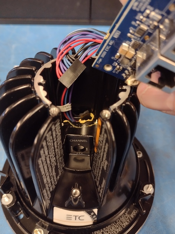
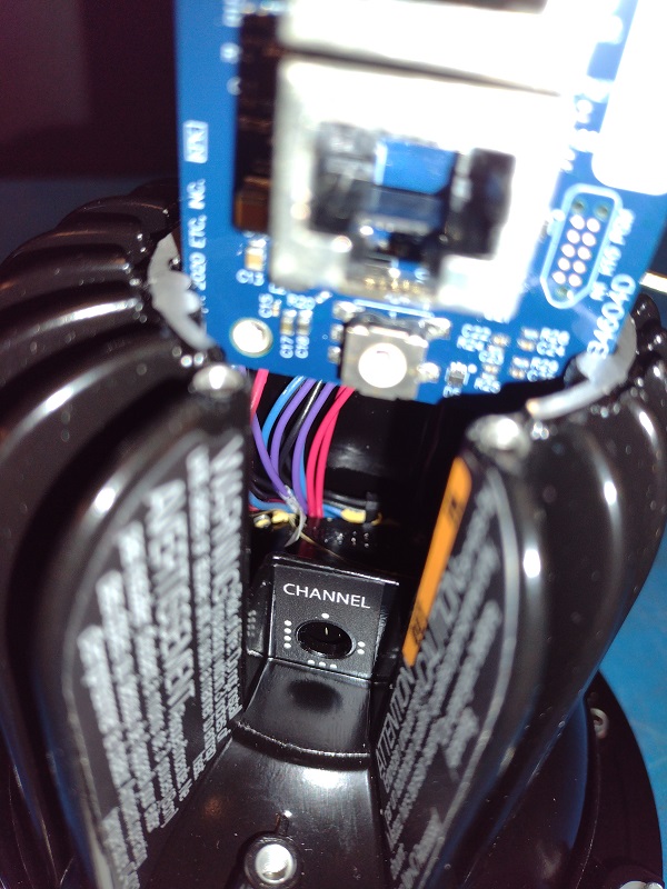
- While holding the control card in position as shown above, turn the fixture over and pull the cables through while pulling/pushing the control assembly into place. Hook the longer harness over the edge of the fixture as you did during disassembly.
- Replace the back cover using the 3 countersink screws.
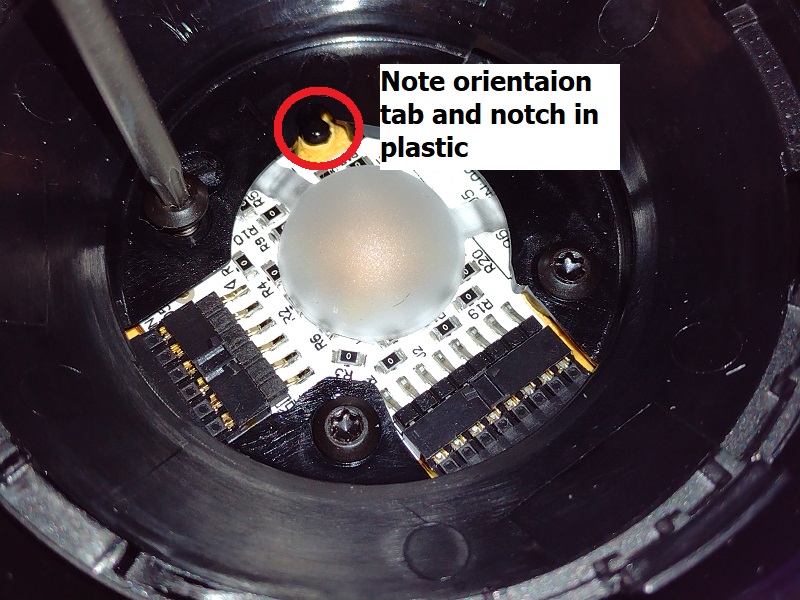
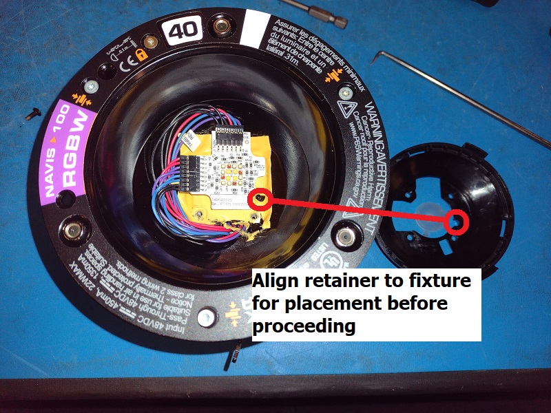
- Turn the fixture over, and examine the plastic lens retainer and it's orientation within the fixture. Note the locating nub sticking up from the thermal pad and it's related notch in the lens retainer. Orient the lens retainer on your table next to the fixture in preparation for step 8 below.
- Reconnect the array making sure to match number of pins to the proper connectors (for RGBW).
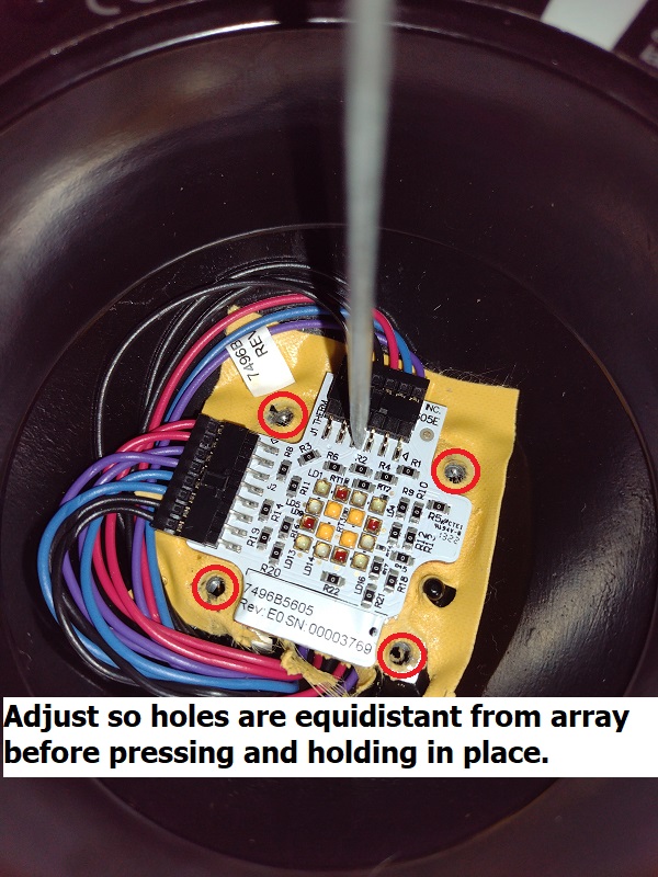
- Gently place the array into place onto the thermal pad using the previous indents to guide you. If you have replaced the thermal pad, place it in a way that is as shown, equidistant to the 4 retention screw holes. Press and hold in place with a finger from one side.
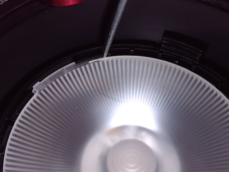
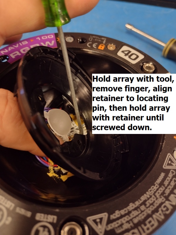
- With the lens retainer in the correct orientation on your desk, hold the array in place with your finger, then place the lens retainer loosely on top. Using a small flat screwdriver or your pick, guide it through the lens retainer as shown to hold down the array while removing your finger and allowing the retainer to drop into place.
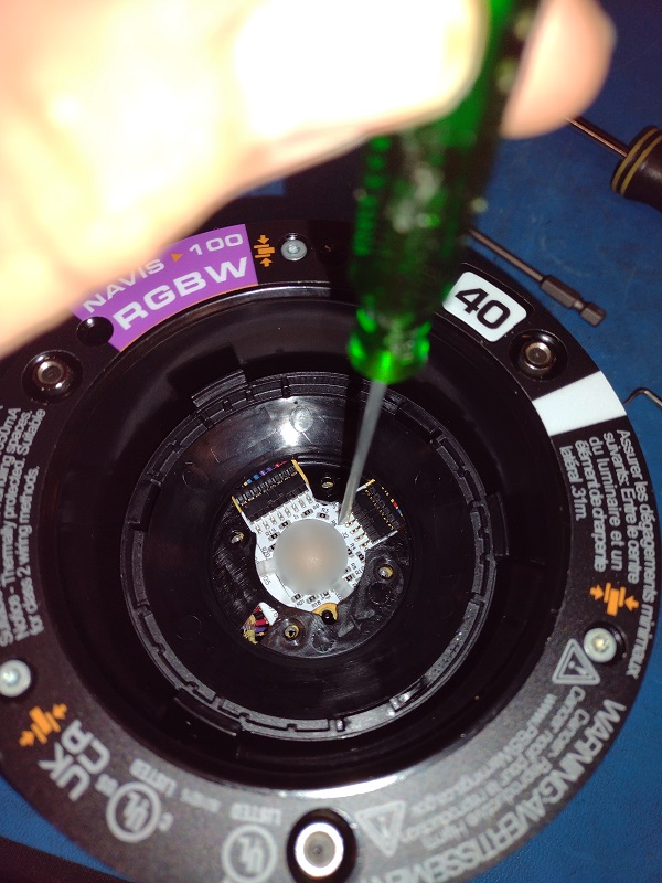
- Now you can remove your screwdriver/pick and use the retainer to hold the array in place while reinstalling the 4 screws. Do not torque them down hard, only use moderate force enough to keep the plastic and array seated.
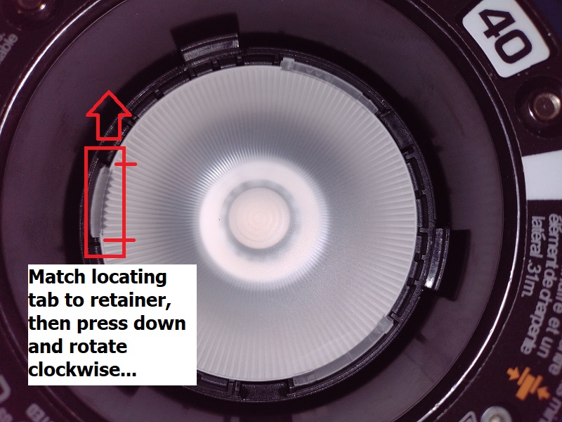
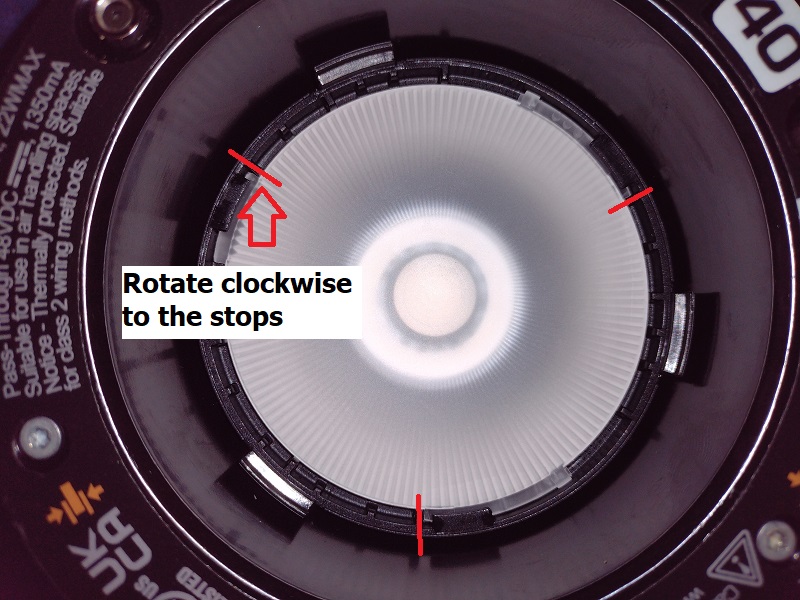
- Gently reinstall the lens by matching up the tabs and rotating clockwise until they reach the stops.