Response 96 Out

Data Input Selection
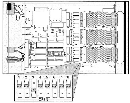
The type of input is defined using DIP switches inside the unit.

| Mode | Switch 1 | Switch 2 |
|---|---|---|
| DMX512 | Open | Open |
| AMX192 | Open | Closed |
| D192 | Closed | Open |
| K96 | Closed | Closed |
Addressing
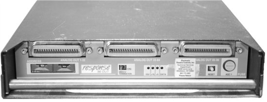
The start address is set using rotary switches on the front of the unit. The switches do not correspond to DMX address but are a multiple of 6 plus 1. Outputs are always consecutively numbered. After changing the address you must reset the unit.
Analog Outputs
Outputs are 0-+10V analog only, on a set of 3 Centronics connectors. Each output can drive up to 10mA current with a maximum of 250mA for the entire board.
Connector 1
Pins 1-32 = Dimmers 1-32
Connector 2
Pins 1-32 = Dimmers 33-64
Connector 3
Pins 1-32 = Dimmers 65-96
All Connectors
Pins 33-34 = Not Connected
Pins 35-36 = Common

RESPONSE 96 OUT
DMX/D192/K96 DATA PINOUT
| 1 | COMMON |
| 2 | DATA - |
| 3 | DATA + |
AMX DATA PINOUT
| 1 | COMMON |
| 2 | CLOCK + |
| 3 | CLOCK - |
| 4 | ANALOG |
ANALOG OUTPUT PINOUT
| 1-32 | CHANNELS (1-32) |
| 35-36 | COMMON |
ADDRESSING
Starting Output numbers can be calculated as shown:
[(1st Output# + 5)/6] = Wheel Setting
i.e. [(13+5)/6]= 03
Outputs are prime numbers.
|
Address |
Output |
|---|---|
| 00 | 01 |
| 01 | 01 |
| 02 | 07 |
| 03 | 13 |
| 04 | 19 |
| 05 | 25 |
| 06 | 31 |
| 07 | 37 |
| 08 | 43 |
and so on...
| DIP SWITCHES | SW1 | SW2 | FILTERS | SW7 | SW8 |
|---|---|---|---|---|---|
| DMX | OPEN | OPEN | NONE | OPEN | OPEN |
| AMX | OPEN | CLOSED | SMALL | CLOSED | OPEN |
| D192 | CLOSED | OPEN | MEDIUM | OPEN | CLOSED |
| K96 | CLOSED | CLOSED | LARGE | CLOSED | CLOSED |
SELF TESTS
| 92 | CHASE |
| 93 | FADE ALL |
| 94 | FADE CHASE |
| 95 | SELECTED OUTPUT TO FULL |
| 96 | ALL TO PERCENT |
TRIM POTS
| P1 | AMX MAX |
| P2 | FULL ADJUST |
| P3 | ZERO ADJUST |
NOTES
- Addressing: [(1st Output# + 5)/6] i.e. [(13# + 5)/6]= 03
- Jumper A off for Opto-isolation (not for AMX)
- Trims are interactive
- 10 mA /output with 250mA/unit max.
- 12Vdc max.
