ETC ColorSource ThruPower installation notes
by Marcus Birkin, Field Service Engineer
The ColorSource ThruPower (CSTP) is becoming an increasingly popular rack of choice for small to medium size power control requirements.
Below are a handful of notes based on some observations in the field, which should assist and inform. Remember that ETC Tech Service is always available for advice and assistance!
This article refers to CE versions of products, with a focus on UK/EU regulations

This note is intended for use by suitably skilled (electrically) persons, local regulations and requirements should always be consulted
Incoming Wiring
The CSTP is provided with 6 incoming lugs, each rated for up to 50mm² cable.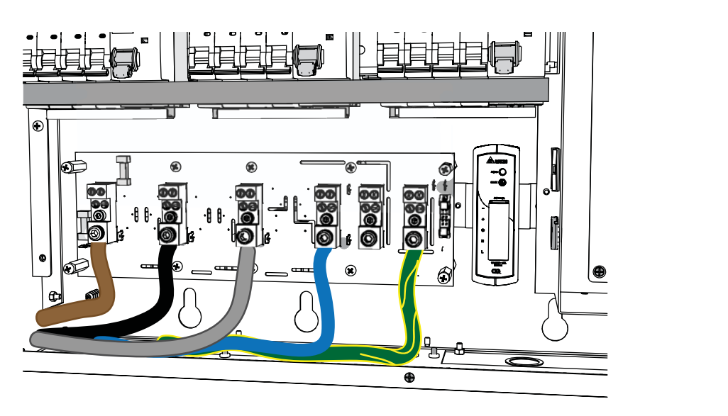
To satisfy the requirements of BS7871:2008+A3 Sec 526 it would be recommended to terminate cabling to these with bootlace ferrules.
Two neutral lugs are provided, these are paralleled/commoned internally.
Should you require the use of only one, they do not need to be externally linked.
- The addition of second neutral lug is for installations requiring larger than 50mm² neutral or where multiple neutrals have been provided.
Final Circuit Wiring
The final circuit wiring is terminated to #6 (3.5mm) screw terminals.
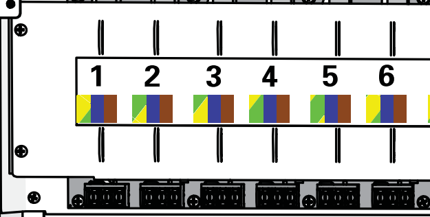
To again satisfy the requirements of BS7871:2008+A3 Sec 526, the use of eyelet crimps is recommended.
- Suitable eyelet crimps are available from RS:
0.5mm² to 1.5mm² (Red) - RS 267-3644
1.5mm² to 2.5mm² (Blue) - RS 267-3789
4mm² to 6mm² (Yellow) - RS 267-3919
Inspection and Testing
Loop Impedance (dead)
When performing R1+R2 loop impedance tests, the following formula should be utilised:
- 0.2ohm is applied to account for the most onerous additional impedance from the internal wiring, triac, and choke combination.
Loop Impedance (live)
If the loop impedance test is performed live, then the test should be performed in with CSTP in always on, relay mode (configured from the UI), and then the final result is derived by the formula:
Insulation Resistance
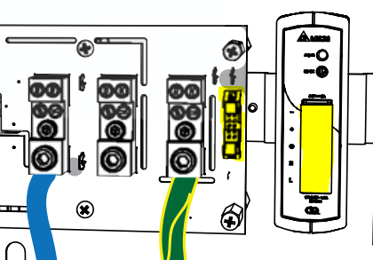
Items vulnerable to damage during an insulation resistance test include the RCDs, triacs, and processor.
To this end the processor PSU and processor should be isolated (connections highlighted below), the incoming line & neutral conductors should be connected together (BS7871:2008+A3 Sec 612.3.1).