Configuring the EM24
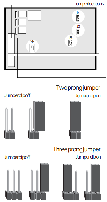 |
Internal jumpers and the front panel thumbwheel allow you to configure several EM24 options and run self tests.A jumper consists of two or three vertical pins on the circuit board. A jumper is on when a clip (a small, rectangular piece of plastic) is placed over two of the pins, closing the circuit. It is off when the clip is removed.
Data Fuses
|
Setting starting address
Set the starting address for your EM24 on the front panel thumbwheel. Select the starting address from the chart below and set the thumbwheels to the corresponding number.
For analog mode, set the starting address to 99. If you need to make changes, write down your original settings for future reference.
| Thumb | Start | Thumb | Start | Thumb | Start | Thumb | Start | Thumb | Start | Thumb | Start |
|---|---|---|---|---|---|---|---|---|---|---|---|
| 00 | 1 | 15 | 85 | 30 | 175 | 45 | 265 | 60 | 355 | 75 | 445 |
| 01 | 1 | 16 | 91 | 31 | 181 | 46 | 271 | 61 | 361 | 76 | 451 |
| 02 | 7 | 17 | 97 | 32 | 187 | 47 | 277 | 62 | 367 | 77 | 457 |
| 03 | 13 | 18 | 103 | 33 | 193 | 48 | 283 | 63 | 373 | 78 | 463 |
| 04 | 19 | 19 | 109 | 34 | 199 | 49 | 289 | 64 | 379 | 79 | 469 |
| 05 | 25 | 20 | 115 | 35 | 205 | 50 | 295 | 65 | 385 | 80 | 475 |
| 06 | 31 | 21 | 121 | 36 | 211 | 51 | 301 | 66 | 391 | 81 | 481 |
| 07 | 37 | 22 | 127 | 37 | 217 | 52 | 307 | 67 | 397 | 82 | 487 |
| 08 | 43 | 23 | 133 | 38 | 223 | 53 | 313 | 68 | 403 | 83 | 493 |
| 09 | 49 | 24 | 139 | 39 | 229 | 54 | 319 | 69 | 409 | 84 | 499 |
| 10 | 55 | 25 | 145 | 40 | 235 | 55 | 325 | 70 | 415 | 85 | 505 |
| 11 | 61 | 26 | 151 | 41 | 241 | 56 | 331 | 71 | 421 | 86 | 511 |
| 12 | 67 | 27 | 157 | 42 | 247 | 57 | 337 | 72 | 427 | ||
| 13 | 73 | 28 | 163 | 43 | 253 | 58 | 343 | 73 | 433 | ||
| 14 | 79 | 29 | 169 | 44 | 259 | 59 | 349 | 74 | 439 |
Selecting incoming data type
The first two jumpers at location J5 on the circuit board (see diagram) determine the type of digital data which your EM24 will receive. After making any changes, press the [Reset] button and the EM24 will reconfigure to match your new settings.
| Data format | Jumper 1 | Jumper 2 |
|---|---|---|
| DMX512 | — | — |
| AMX192 | on | — |
| Micro II | — | on |
| Preset control | on | on |
Additionally, if you are using Colortran data, set the top pair of pins in the three-way jumper at location J4 to On. For all other formats, connect the bottom pair of pins. If you are receiving AMX192 data, set the top pair of pins in the three-way jumper at location J3 to On. For all other formats, or if you are running self tests, connect the bottom pair of pins. Use the Preset Control setting if your EM24 is in an L86 Wall Pack using wall mounted control stations.
Setting number of outputs
Set Jumper 3 at location J5 to Off to if you have twelve 2.4k or twenty four 1.2k dimmers. Set it to On to if you have six 6k dimmers.
Setting line frequency
Set Jumper 4 at location J5 to Off for 60 cycle frequency. Set it to On for 50 cycle frequency.
Setting Dimmer Phasing
The red slide switch at location S5 controls the phase setting for your EM24. If your pack is wired for three phase operation, set the switch to the right (front panel facing you). Set the switch to the left for single phase operation.
right = 3 phase 120/208 4-wire
left = 1 phase 120/240 3-wire