EM24 Front Panel
The EM24 front panel contains a set switch, five indicator LEDs, an address select thumb wheel, and, on the EM24D, input control connectors. These features provide you with information about and access to your dimming system as indicated below.
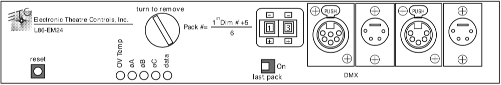
Indicator LEDs
Each indicator LED on the EM24’s front panel provides specific information about the operating status of the EM24 electronics.The information each LED provides is described below.
- OVTemp
LED Off Normal
LED On Pack is overheated, or the remote reset line is grounded.
Note: If this LED is on, all out puts are turned off.
- ØA,ØB,ØC
LED On Phase is receiving power.
LED Off Phase is not receiving power.
Note: LED will be off if the EM24 is in single phase operation.
- Data
LED Off Analog mode is selected.
LED On System is receiving digital data.(Normal)
LED Flashing Digital data input mode is selected, but no digital data is being received.
Note: When DMX512 input is interrupted, the EM24 maintains the last valid output levels it received for four minutes, then fades all outputs tozero. When AMX192 data is interrupted, the outputs will fade immediately.
Reset switch
Pressing [Reset] causes the system tore start. At this point, the system will reconfigure it self to match current settings. [Reset] should be pressed anytime the starting address is changed, and anytime an EM24 is installed into a system which has already been turned on.
Thumb wheel address switch
The thumb wheel is used to set starting addresses for your dimmers, as well as to select self tests.(See Setting Starting Address on page 3 and Self Test Mode on page 4.)
Termination switch
The Termination switch identifies the EM24 which is at the end of the chain of packs. The switch should beset to On for the last EM24 in the DMX512 chain. All others should be set to Off.
Note: Switch should be set to Off for AMX192 mode.
Data connectors(optional)
Input/Output jacks for various protocols. Pinout:
| DMX512 | AMX192 |
| 1 Common | 1 Common |
| 2 Data- | 2 Clock+ |
| 3 Data+ | 3 Analog Multiplex |
| 4 Analog Multiple | 4 Clock- 5NoConnection |