Configuring the EM64
|
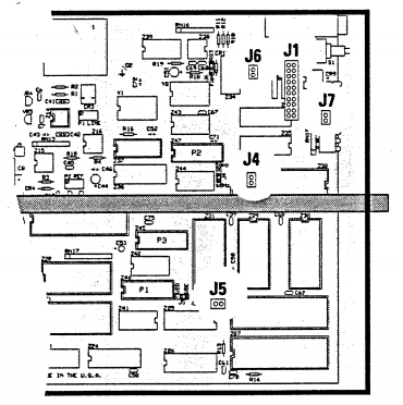
EM64 jumper locations
Two Prong Jumper Use these jumpers to set starting address |
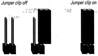
Internal jumpers allow you to configure EM64 options and run self tests. A jumper consists of a pair of vertical pins on the circuit board. A jumper is On when a jumper clip (a small. rectangular piece of plastic with two sockets) is placed over both connectors, closing the circuit. It is Off when the clip is removed. Jumper locations are shown on the EM64 circuit panel diagram. Each jumper location is marked with a J.
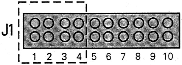
Setting starting addressJumpers 1 through 4 at location J1 set the starting address for the EM64. Select the starting address by setting the jumpers according to the chart below. The starting address and the dimmer number (as listed on your console) do not necessarily corre spond. If you need to make changes. write down your original jumper settings for future reference. If your system has the optional front panel thumbwheel address switch. you can use it to select a starting address.
|
||||||||||||||||||||||||||||||||||||||||||||||||||||||||||||||||||||||
|
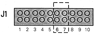
Use Jumpers 6 and 7 to select dimmer module type |
Selecting dimmer module typeSet Jumpers 6 and 7 at location J1 to indicate the smallest dimmer installed in your chassis. For example, if the chassis contains both Bk and 1k dimmers. set the jumpers to the 1k setting.
|
||||||||||||||||||||||||||||||||||||||||||||||||||||||||||||||||||||||
|
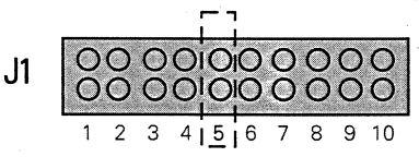
Use Jumper 5 to set line regulation |
Setting line regulationLine regulation maintains lamp intensity at a constant level. even if power line voltage fluctuates. Set Jumper 5 at location J1 to Off to allow normal line regulation. Set it to On to disable line regulation. |
||||||||||||||||||||||||||||||||||||||||||||||||||||||||||||||||||||||
|
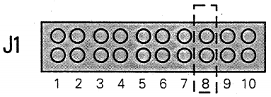
Use Jumper 8 to set backup mode |
Setting backup mode (analog)Some EM64s have the optional ability to accept analog input. If you have this option, set Jumper 8 at location J1 to Off to disable digital mode and select the backup (analog) mode. For normal digital input, this option is set to On. |
||||||||||||||||||||||||||||||||||||||||||||||||||||||||||||||||||||||
|
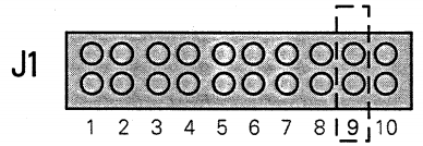
Use Jumper 9 to enable Soft start |
Enabling Soft startSoft start is an option that adds a dynamic filter to reduce lamp shock, caused by turning a lamp on to full when the bulb is cold. Jumper 9 at location J1 enables the Soft start option when set to Off. Set Jumper 9 to On for normal operation. |
||||||||||||||||||||||||||||||||||||||||||||||||||||||||||||||||||||||
|
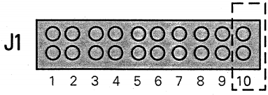
Use Jumper 10 to enable Self test |
Enabling Self test modeThe EM64 allows you to specify a number of built-in self tests. If you wish to run one of these self tests, set Jumper 10 at location J1 to On. The next time you restart the module or turn the system on, the EM64 will run the self test you require. |
||||||||||||||||||||||||||||||||||||||||||||||||||||||||||||||||||||||
Use jumper at J7 to enable Preheat mode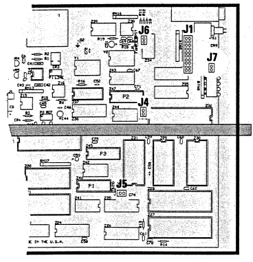 |
Enabling Preheat modeIn Preheat mode, the EM64 maintains all dimmers at a minimal level even when the dimmer is turned all the way down. This can prolong the life of your lamps by protecting the filaments. Please note that if your rack contains modules with indicators, the Preheat mode will make them glow at all times. Jumper 1 at location J7 enables Preheat when set to On. Set the jumper to Off for normal operation. |