Configuring the EMR/EMAR
 |
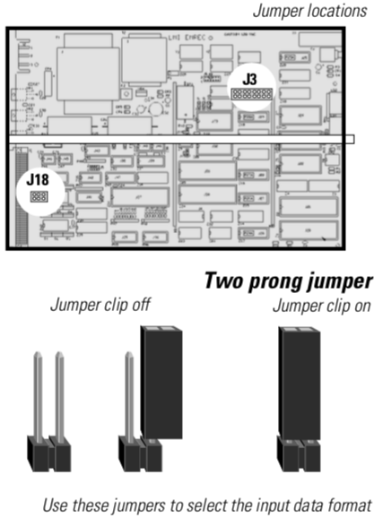
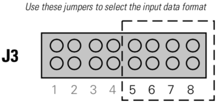
Most L86 Installation Racks and some L86 Touring Racks are shipped with specially customized programming and non-standard jumper settings for their EMR/EMAR modules. The following section describes jumper settings and configuration options for non-customized systems only, except where noted. Customized systems include a separate sheet noting your actual settings. If you have any questions, please contact ETC Technical Service at 608/831-4116. The modules are configured by adjusting settings on a bank of jumpers within the module. Jumpers consist of either two or three vertical pins on the circuit board. A two-pin jumper is On when a clip (a small, rectangular piece of plastic) is placed over both connectors closing the circuit. It is Off when you remove the clip. A three-pin jumper is On with the center pin connected to either of the side pins. It is Off when the clip is removed. If the module malfunctions and you need to exchange it for a spare, be certain to adjust all the jumper settings on the spare so they match the settings on the original module. The circuit board illustrations on page 4 show the locations of all jumpers. Selecting input data formatJumpers 5 through 8 at location J3 allow you to select the incoming data format for the module. Select the format by setting the jumpers according to the chart below. |
|||||||||||||||||||||||||||||||||||||||||||||||||||||||
 |
|
|||||||||||||||||||||||||||||||||||||||||||||||||||||||
|
Custom is the most common configuration for L86 racks. If you have a customized system, your System Manual includes a separate page showing your actual EMR/EMAR jumper settings. K96 supports ten backups with 256 dimmers in each. AMX192 signals have filters to remove excess noise. The EMR lets you merge two incoming DMX512 signals into a single output signal. The EMAR also lets you merge an incoming signal using a different protocol with a DMX512 signal into a single DMX512 output. The chart below indicates the jumper settings for signals that combine the output types shown in the left column.
|
||||||||||||||||||||||||||||||||||||||||||||||||||||||||
 |
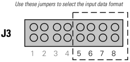
Jumpers 1 through 4 at location J3 allow you to set the starting address for the EMR/EMAR. Select the starting address by setting the jumpers according to the chart below. Please note that the starting address and the dimmer number (as listed on your console) do not necessarily correspond. If you need to make changes, write down
|
|||||||||||||||||||||||||||||||||||||||||||||||||||||||
 |
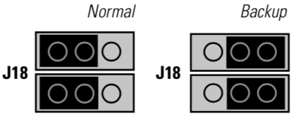
Backup jumpersIf your module fails, you can temporarily continue to use the rack by setting the module to Backup mode. Do this by changing the jumper settings at location J18 from Left to Right (as shown to the left). You can also replace it with the EMRF module shipped with your system for that purpose. |
