Sensor Rack Phasing
What is Phase Balancing?
Phase balancing refers to the way in which the circuits are landed in the rack. There are two ways which a Sensor rack can be phase balanced: straight or balanced.
- Straight: Circuits are numbered from top to bottom straight down the rack. This is mainly used in architectural and touring situations.
- Balanced: The circuits are evenly distributed across the phases. That way circuits can be sequential on a location or postilion but are evenly distributed across the phases
Unison DRd racks can be balanced as well, but since they are mainly used for architectural systems, they are often straight.
The information in this article applies only to three-phase racks. Single-phase racks (also called biphase or split-phase racks, with 2 hots) are balanced differently. Single-phase racks are uncommon; most are touring racks/packs and some are smaller install racks (SR24 or smaller).
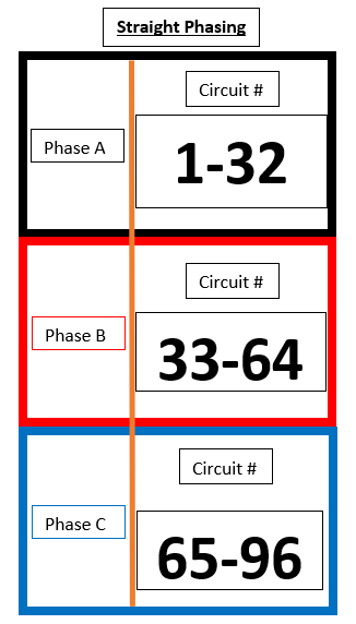
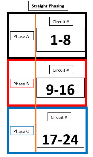
Straight Phasing in an SR48
In the Straight Phasing example below circuits:
- 1 - 32 land on phase A
- 33- 64 land on phase B
- 65-96 land on phase C
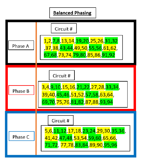
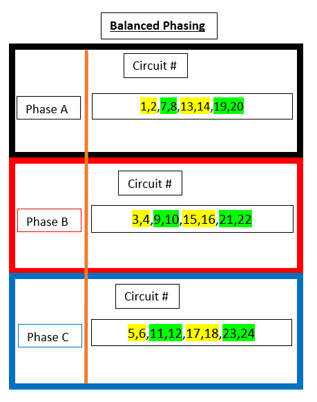
Balanced Phasing in an SR48
In Balanced Phasing circuits are not in numerical order, and are distributed equally between the phases:
- Phase A contains circuits 1,2,7,8...
- Phase B contains circuits 3,4,9,10...
- Phase C contains circuits 5,6,11,12...
Green and Yellow highlights are used illustrate a single density dual circuit module, such as a D20 or R20.
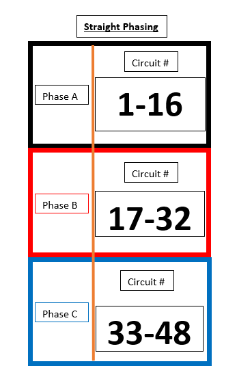
Other Rack Types
The other rack sizes use the same distribution of circuits, but the numbering is slightly different due to the different quantity of dimmers available.
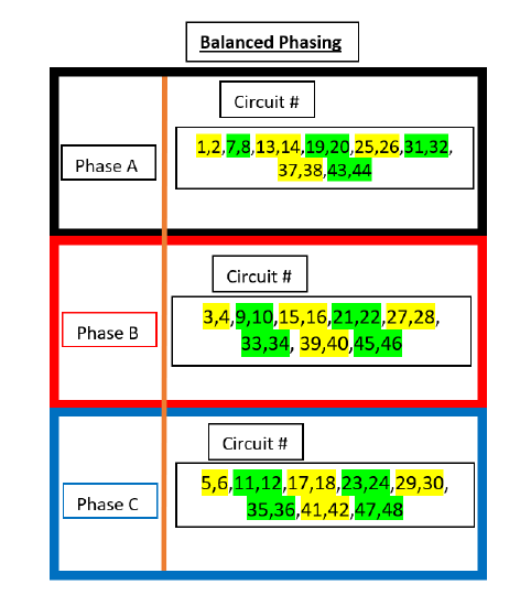
SR24
Green and Yellow highlights are used illustrate a single density dual circuit module, such as a D20 or R20.
| SR24 (Straight) | SR24 (Balanced) |
|---|---|
 |
 |
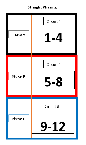
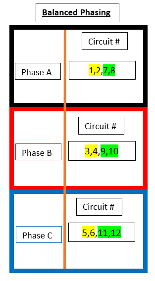
SR12
Green and Yellow highlights are used illustrate a single density dual circuit module, such as a D20 or R20.
| SR12 (Straight) | SR12 (Balanced) |
|---|---|
 |
 |
SR6
Green and Yellow highlights are used illustrate a single density dual circuit module, such as a D20 or R20.
| SR6 (Straight) | SR6 (Balanced) |
|---|---|
 |
 |
Below is a video that walks through the basics of rack phase balancing.
Sensor Rack Phasing Spreadsheet
Here is a link to an Excel Spreadsheet that will automatically readdress a rack and show you the phase balancing, distro cards, and AF cards. It's a great tool for troubleshooting. NOTE: it includes a 36/72 rack which is mainly used Europe and Sensor Classic touring.