Pantograph Guide
Overview
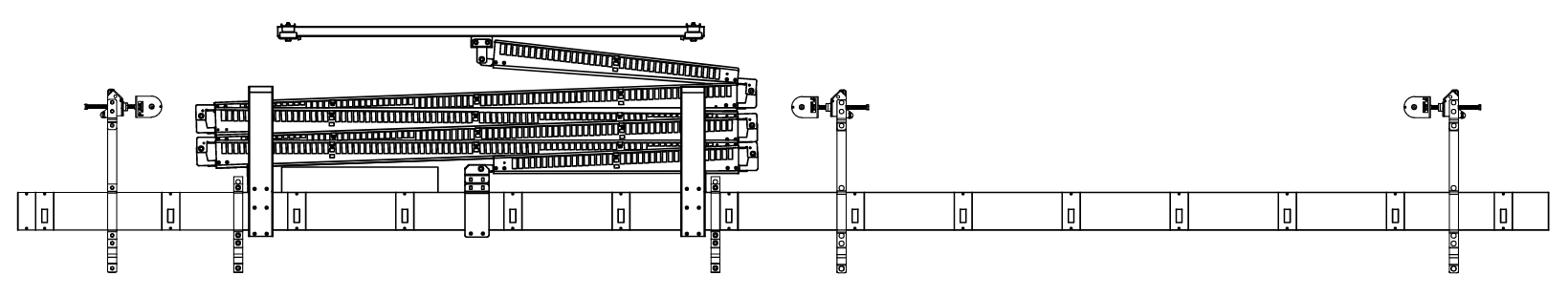
ETC’s Pantograph Cable Management System is a customizable cable management solution for stage electrics, front of house lighting positions, and other applications where power and/or control circuits need to be brought down to a motorized batten.
Variants
Standard Distro Mount – The pantograph hinge and support brackets mount directly to ETC 9900 Series Distribution Strips.
- The standard distro mount pantograph assembly has 4'-0" of festoon/low voltage cable from the bottom hinge assembly for factory termination to the distro strip terminal box.
Pipe-mount – The pantograph hinge and support brackets mount directly to an industry standard 1.5” Schedule 40 pipe. The pipe-mount pantograph can mount to the top pipe of a dual pipe electric, to the batten for an orchestra shell ceiling section, or other motorized battens within a venue.
- Bare-End – The pantograph assembly can be provided with bare end festoon cables/low voltage cables at the bottom of the pantograph for termination to an ETC Connector Strip in the field.
- The distro strip must be built with a pantograph specific terminal box with a strain relief bracket specific to the flat festoon cable.
- The standard pip-mount pantograph assembly has 6'-0" of festoon/low voltage cable from the bottom hinge assembly for field termination.
- Pipe-mount Terminal Box – A pipe-mount terminal box can be provided at the bottom end of the pantograph to allow for field termination to an existing or 3rd party distribution strip.
Travel - Standard Pantograph Assemblies up to 79’ of vertical height (combined travel + dead hang) are available.
Linear Slide Assembly – The top hinge point of the pantograph attaches to a carrier that travels parallel to the pantograph assembly as the pantograph folds/unfolds during travel. The carrier reduces the amount of sway in the system.
- Compression Tube Mount – When paired with a Prodigy hoist with Compression Tube the linear slide assembly mounts directly to P1 or P75 Compression Tube.
- Strut Mount – A 10’ section of P1001 (back-to-back) Unistrut is used for the linear slide assembly and provides mounting flexibility in the field. Mounting hardware and additional structure/material required for mounting the strut to the building structure is provided by others.
Required Information
The following information is required to provide submittal drawings and create bills of material prior to assembly in Manufacturing. (See Guidelines below for additional information.)
- Total Vertical Dead Hang + Travel Distance
- Number of Circuits & Low Voltage Cables/Type
- Linear Slide Assembly Mounting
- P1 Compression Tube, P75 Compression Tube, or strut-mount
- Pantograph Hinge & Vertical Support Bracket Mounting (9900 Series Distro Mount or Pipe-Mount)
- Lower Cable Termination Method
- ETC distro, bare end, terminal box, etc.
Guidelines
Travel + Dead Hang - The total distance from the mounting steel to the low trim position is required to provide the correct length pantograph assembly.
Circuit Count & Low Voltage Cables
Power Circuits - Festoon Cable
- 16 Circuits at 20 A. max each
- 17 – 24 circuits at 50% Electrical Diversity
- The Stage Pantograph – Diversity Requirements Over 16 Circuits.
- The following KMS article provides additional information on circuit diversity: Stage Pantograph - Diversity Requirements Over 16 Circuit
- Festoon Cable Length from Top Hinge to FCTB: 10'-0" + 2'-6" for FCTB Termination
- Festoon Cable Length from Bottom Hinge to attached distro term box: 4'-0" + 1'-6" for pantograph mounted term box termination
- Festoon Cable Length from Bottom Hinge to pipe-mount distro term box: 6'-0" + 2'-6" for pipe-mount strip termination
Low Voltage Cable & Types
- The maximum number of low voltage cables in a pantograph assembly varies in relation to the total number of circuits.
- The Flat Cable Term Box (FCTB) used with pantograph cable management has a maximum of:
- 4 DMX runs - or -
- 4 DMX runs and 2 network runs (Cat5e -> Cat6A) - or -
- 2 DMX runs and 3 network runs - or -
- 4 network runs
- For pantograph cable management systems with a smaller number of power circuits, additional low voltage can be accommodated with a second FCTB or a custom low voltage grid box.
Lift Line Spacing – A minimum of 10’-0” is required between lift lines for proper clearance on either end of the pantograph assembly.
Vertical Support Brackets & Additional Hanger Brackets
- Extended RACAs/Hanger brackets should be used to keep the hanging point above the center of gravity of the cable management system for added stability and to prevent batten rolling.
- RACAs/Hanger Brackets need to be spaced at a maximum of 8’-0” apart.
- If Lift Lines are spaced up to 8’-0” apart an additional hanger bracket is not required.
- A hanger bracket is required adjacent to each pantograph vertical support bracket.