PixelMap compound fixtures on Hog 4
Note this guide is not intended to be a general plotting or pixel mapping guide, for more information, consult the Hog 4 user manual or the High End Systems YouTube Series.
Understanding a Compound Fixture
A compound fixture (Also known as a multiple part, cell, or instance fixture) Is a fixture with multiple fixture types put together into a single fixture. Compound fixtures usually have multiple sections of emitters or modules, like an LED bar, or a multi cell wash/FX light. These parts are generally controlled with dotted user notation. Compound fixtures sometimes will have a "master" whole number and multiple parts that are controlled by decimal numbers. Compound fixtures generally have several modes, sometimes listed as compact, simple, basic, standard, extended, etc. Not all modes are mappable. To see the parts of a compound fixture, schedule the fixture in the fixture window, and press "Show Details" which will show an expanded view of the parts of the fixture.
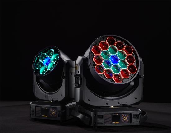
Pictured above left: High End Systems SolaPix 7 and 19
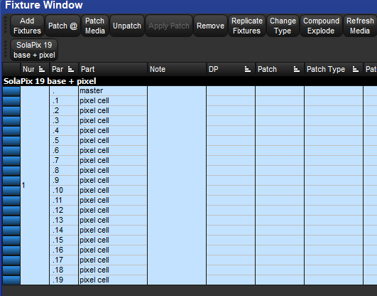
Pictured above right: High End Systems SolaPix 19 as viewed from the Fixture Window, note the master (1.) and the 19 cells (1.1 thru 1.19)
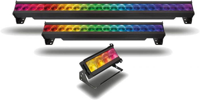
Pictured above left: Chroma-Q Color Force II 12, 48, and 72
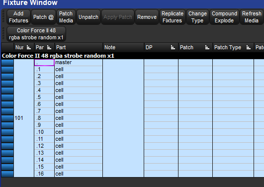
Pictured above right: Chroma-Q Color Force II , 48, as viewed from the Fixture Window, note the master (101.) and the 19 cells (101.1 thru 101.16)
Creating A Plot
The following example will guide how to make a plot of 10 SolaPix 19's.
The SolaPix 19 parts include
Master: #
Center RGBW cell #.1
Middle ring RGBW cells #.2>#.7
Outer ring RGBW cells #.8>#.19
The master section will not be included on the plot. This is important, as masters should not usually be mapped, as they can override cell values.
Record and open a plot without any fixtures assigned to it.
[Clear] [Record] (Plot 1)
Hold [Open] and press (Plot 1)
Maximize window if needed
Add a linear gang of just the middle cells
Ensure the Gang Edit Lock is on
[1] [Thru] [10] [Enter] [.][1] [Enter]
Select the Add Linear Gang tab
Draw the gang across the plot.
Re-size and center the gang
Ensure the Gang Edit Lock is on
Select the gang
Set the X and Y coordinates to 0,0
Set the width to 2000 units
Set the rotation to 0°
Press Show All as needed
This will ensure a centered, evenly spaced and level gang to start off with.
Draw the the middle rings as individual circle gangs.
Ensure the Gang Edit Lock is on
[1] [Thru] [10] [Enter] [.][2] [Thru] [.][7] [Enter]
Select the first of the sub selection by holding [Fixture]&[Next]
Select the Add Gang tab in Circle Mode
Draw the gang over the first fixture
Select the next fixture middle ring by holding [Fixture]&[Next]
Select the Add Gang tab in Circle Mode
Draw the gang over the second fixture
Repeat until a rough gang has been added over each fixture
Align and resize the middle rings
Ensure the Gang Edit Lock is on
Select the circle gangs
Set the Y coordinate to 0
Set the Width and Height to 50
Enable the plot grid and set the unit spacing to 100 units
Drag the circle gangs so they center up with the center cells.
Press Show All as needed
Draw the the outer rings as individual circle gangs.
Ensure the Gang Edit Lock is on
[1] [Thru] [10] [Enter] [.][8] [Thru] [.][19] [Enter]
Select the first of the sub selection by holding [Fixture]&[Next]
Select the Add Gang tab in Circle Mode
Draw the gang over the first fixture
Select the next fixture middle ring by holding [Fixture]&[Next]
Select the Add Gang tab in Circle Mode
Draw the gang over the second fixture
Repeat until a rough gang has been added over each fixture
Tip: It might be easier to draw the rough gangs above the existing fixtures, as it will be easier to select them in the next step.
Align and resize the outer rings
Ensure the Gang Edit Lock is on
Select the circle gangs
Set the Y coordinate to 0
Set the Width and Height to 100
Enable the plot grid and set the unit spacing to 100 units
Drag the circle gangs so they center up with the center cells.
Press Show All as needed
Adjust Cells Shape and Size (Optional)
Ensure the Fixture Edit Lock is on
Select the Fixtures by clicking and dragging over them on the plot
Change the shape to hexagon
Change the size to the preferred size.
Press Show All as needed
Draw the PixelMap Layer
Ensure PixelMap Layers are added to your show. PixelMap Layers are added like any other fixture in the fixture window
Ensure the PixelMap Layer Edit Lock is on
Select the Add PixelMap Layer tab
Draw the PixelMap Layer across the plot.
Select the PixelMap Layer
Set the X and Y coordinates to 0,0
Set the Width to 2000 units
Set the Rotation to 0°
Press Show All as needed
This will ensure a centered, evenly spaced and level PixelMap Layer
Assign the PixelMap Layer to 100
Playback Content!
Select the Fixtures [1] [Thru] [10]
Select (Plot 1) [Enter] (Shortcut for plots window [PIG]&[Open]&[Fixture]
Select [100] [@] [Full]
Select PixelMap content from the Media Picker (Shortcut for media picker [PIG]&[Open]&[Beam]
How To Create a PixelMap Per Fixture (Optional)
Copy the existing plot to a new plot
(Plot 1) [Copy] (Plot 2)
Open the copied plot [Open] (Plot 2)
Ensure the PixelMap Layer Edit Lock is on
Select the existing PixelMap Layer and delete it
Draw the PixelMap Layers
Ensure the PixelMap Layer Edit Lock is on
Select the Add PixelMap Layer tab
Draw a PixelMap Layer across the first fixture
Repeat for the following fixtures
Select the PixelMap Layers
Set the Y coordinates to 0
Set the width to 120 units
Set the height to 120 units
Set the rotation to 0°
Enable the plot grid and set the unit spacing to 100 units
Drag the PixelMap Layers so they center up with the fixtures
Press Show All as needed
This will ensure centered, evenly spaced and level PixelMap Layers
Assign each of the PixelMap Layers to 101 thru 110
Tip: Some programmers like to assign their PixelMap Layers to dotted user notation in regard to the plot they are using. In this case, the PixelMap Layers might be 2.1 >2.10
Playback Content!
Select the Fixtures [1] [Thru] [10]
Select (Plot 2) [Enter] (Shortcut for plots window [PIG]&[Open]&[Fixture]
Select [101] [Thru] [110] [@] [Full]
Select PixelMap content from the Media Picker (Shortcut for media picker [PIG]&[Open]&[Beam]
Modify individual Layers as needed