R20 Modules in Unison Legacy DR Racks
- Last updated
- Save as PDF
In order to use R20 (20A Relay Modules) or LED10 (PhaseAdept) in Unison Legacy DR racks, a signal distribution card with a neutral reference must be present.
If there is no neutral wire in the rack and an R20 or LED10 is installed, the modules will not turn on but their signal LEDs will respond as if they have.
R20s/LED10 require a neutral reference to operate properly. This reference is provided by the signal distribution card via a wire connected to the neutral bus. If you see signal lights on your R20/LED10 modules, but there is no power to the circuit, you may have either a disconnected neutral reference wire, or your DR rack may be old enough that it does not have one at all.
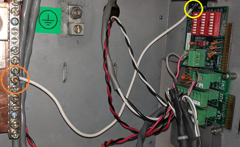
To determine if your rack has a neutral reference signal distro card, you will need to first power down the rack entirely and remove the processor and the bottom few modules of the rack. The signal distribution card is the circuit board that runs the length of the right side of the DR rack. Near the bottom of this card you should see a small white wire soldered on if the neutral reference is present.
Warning: Do not remove the Unison processor or any dimmer modules without first powering off the dimmer rack at its breaker. Failure to do so may result in injury or damage to your equipment.
This neutral reference wire was added to Unison DR racks in mid-June 2000.


- If your rack does not have this neutral reference wire then the signal distribution card will need to be replaced with a newer version. The neutral line cannot be connected to the older card as a solder location is not present.
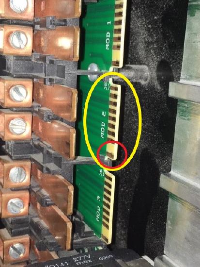
- If the neutral reference wire is present but you are still having this issue, the signal distribution card could be damaged, not allowing the neutral reference to make it all the way to the module. To test this, you will need a multi meter set to continuity test. Place one meter lead on the neutral bus bar where the reference wire is landed (see orange circle in image above) and the other lead on the circuit board in the problem slot. Place that lead on the bottom gold finger on the circuit board, noted in the red circle in the image below. If there is no continuity from the neutral bus bar to this pin, the signal distribution card will need to be replaced.

To have a new card installed, please contact your local ETC dealership.
The parts needed are as follows:
For a DR6 7083B5604
For a DR12 7083B5603
