
Mosaic MSC X Network Ports Explained
The information in this post is provided to assist in troubleshooting. Perform work at your own risk. ENSURE ANY POWER FROM DEVICES HAS BEEN DISCONNECTED BEFORE SERVICING ANY EQUIPMENT. If you do not feel comfortable performing the work, please contact us or your local service center. Be aware that ETC and its Affiliates are not responsible for any damage or injury caused by service of our products by anyone other than us or our authorized service providers, and such damage is excluded from the product’s warranty.

The Hardware
MSC X and Atlas controllers feature (2) network ports on the rear of the controller.
The Management port labeled as 'MGMT' can be found on the rear far left hand side of the controller.
The Data port labeled as 'DATA' can be found on the rear left hand side of the controller nearest to the DVI Output connection.
MSC X & Atlas

Atlas Pro controllers feature one 'MGMT' port two 'DATA' ports.
Important considerations should be observed before using the 2 output ports on the Atlas Pro controller. These considerations are discussed later in this article.
The Management port labeled as 'MGMT' can be found on the rear far left hand side of the controller.
The Data ports labeled as 'DATA' can be found on the rear left hand side of the controller nearest to the DVI Output connection.
Atlas Pro

ETC recommends setting the management and output ports on different IP schemes and subnets.
Separate IP schemes are recommend to prevent protocols 'cross-talking' across networks.
Management Port
The Management port is responsible for the following communications:
- Mosaic Designer 2 communication
- Firmware Updates
- Configuration upload and download
- Paradigm communication
- Indication Triggers
- Paradigm Actions
- Ethernet Input Triggers
- API
- HTTP
- Lua
- JavaScript
Data Ports
The Data ports are responsible for sending lighting protocol data and handling network based DMX triggering
- Protocol Outputs
- sACN
- When using the Atlas Pro controller, sACN is sent on all output ports,
- KiNet
- When using an Atlas Pro controller, KiNet data will be sent out through the output port on which the target device's MAC was discovered.
- Art-Net
- When using an Atlas Pro controller, Unicast data will be sent out through the output port on which the target device's MAC was discovered.
- When using an Atlas Pro controller, Broadcast data will be sent out of both ports.
- sACN
- DMX Input Triggers
- sACN
- Art-Net
Understanding the Atlas Data Ports
As Atlas Pro has (2) output ports, there are considerations that must be taken into account before the ports are connected to a site network. The (2) ports are intended to be used in systems that require (2) separate distribution points for lighting data.
Output ports 1 and 2 are internally connect via single logical port on the inside of the controller.
As such, only a single IP address can be assigned to the (2) output ports on the Atlas Pro controller, because of this, it is important the two output ports are NOT connected to same switch as this can cause a network loop.
Network Port Configuration
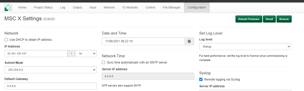
Management Port can be configured in two different spots (Mosaic Designer 2 and the WebUI)
- Mosaic Designer 2 > Network Tab > Right-Click on the MSC X > Configure
- Change the Network settings here.
- The Management Port should be aligned with your other ETC devices on the network. For example, the default ETC IP scheme is 10.101.x.x.
- As shown above, this IP is how MD2 will see the controller and what IP address you will use to get to the WebUI.

- WebUI > Configuration Tab
- Just like above, change the Network IP settings here.
Data Port can only be configured in Mosaic Designer 2 while the project is open.
- Network Tab > Select the MSC X from the Controller List.
- On the right side, select the Protocols Tab
- The header labeled Network 2 (Protocol) is the Data Port on the back of the MSC X.
- This IP Address must be in a different IP Scheme than that of the Management Port. For example if the MGMT port is at 10.101.x.x, the Data port could be at 192.168.x.x.

- sACN output will still be present to the 10.101.x.x side because the sACN receivers are looking for multicast at 239.255.x.x. The IGMP Querier on a network switch will direct the sACN traffic from the source at 192.168.x.x to those 10.101.x.x ports that are asking for it. A quick way to observe this is to setup the MSC X and start sACNView on a computer with a 10.101.x.x scheme and notice the source is actually 192.168.x.x. The screenshot from sACNView below shows this.
- In this screenshot, the host computer has IP address 10.101.19.20, the MSC X Management port is 10.101.120.101, and the MSC X Data port is at 192.168.1.1.

- The wireshark snapshot below, taken from the same PC as above also shows the PC telling the IGMP querier that it is interested in universe 101 in addition to it receiving all the standard sACN packets for universe 101.
