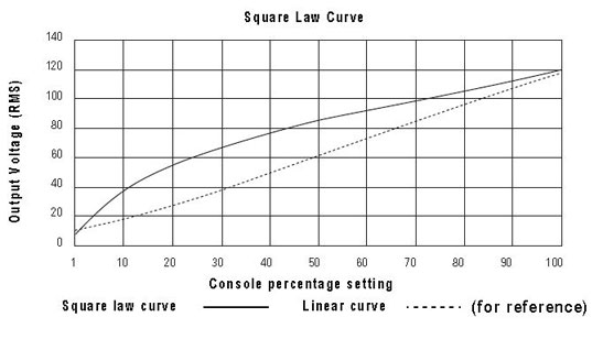
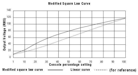
Dimmer curves determine how dimmers set voltage output in response to control signal input. To accommodate designer preferences and load response variations, Sensor offers five dimmer curve choices, which can be applied to individual dimmers.
Square law curve
At low control levels, much of a traditional incandescent fixture's light output is in the invisible infrared spectrum. This results in poor visible response to low control levels. A square law curve applies a multiple derived from the square root of the control level (with full output equal to 1.00) to increase voltage response at low control levels to compensate for the infrared loss.

Modified Square law curve
A standard square law curve may overcompensate for infrared loss, resulting in "steppy" response to incremental control changes at low levels. ETC's modified square law curve applies a second multiple to the standard square law curve for more uniform response to control level changes across the entire range of dimmer output.
