QSC Q-SYS Unison Paradigm Plugin Help
Contents
Introduction
Thank you for choosing to integrate with ETC's Unison Paradigm architectural lighting control system. Please click here to learn more about Paradigm's product offerings. Please contact aesupport@etcconnect.com with any technical questions you may have regarding this Q-SYS plugin package.
Summary
The Q-SYS plugin package consists of six *.qplugx files and two example Q-SYS Designer files as a reference. The modular design of the plugins allow you to have virtually unlimited scaling ability for your project design. Directly control Paradigm presets, channels, groups, macros and walls. Each control plugin has the capacity to control up to 100 Paradigm objects. If you need more controls of a specific type simply drag in another control plugin instance into your schematic.
Please keep in mind the more objects that are allowed within the plugin the longer it will take the plugin's control object tab to display within Designer. If 100 objects are allowed it will take Designer approximately 5 seconds to open the tab....please be patient.
Paradigm PSAP object triggers need to be setup to allow for automatic status updates within the Q-SYS system....please coordinate with the projects's ETC Field Engineer. If this is not done Paradigm controls within Q-SYS will not update when a user interacts with Paradigm. The Q-SYS plugins do have the ability to poll the Paradigm system for status and will when the Q-SYS design is loaded to the core controller provided that option is enabled within the plugins.
Release Notes
- V2.0
- Added ability (optional) to import object/space data into plugin from a spreadsheet (standard CSV format supported-[non-UTF])
- I/O Handler auto detects available NICs within the Core
- Added I/O Handler Ethernet retry timer
- Added connection status output pin to I/O Handler
- Moved help page tab to the far right of UI so the plugin controls are the first to be exposed when the plugin is opened
- When default object/space name fields are empty they will now automatically repopulate with default text
- Commands will not be sent from the Q-SYS Core when object/space name fields contain default text
- Fixed nil arithmetic issue within channel/group level display selection dropdown
- Tested with the following firmware versions
- Q-SYS V9.7.0
- Paradigm V5.0.3
- V1.0
- Initial Release
- Tested with the following firmware versions
- Q-SYS V9.3.1 & V9.4.0
- Paradigm V4.2.4 & V5.0.1
Getting Started
There are two ways to install the plugin package. Either double click each *.qplugx file or install through Q-SYS Designer's Asset Manager.
Once the plugins are properly installed drag in an instance of the I/O Handler plugin into your schematic. There must be at least one I/O Handler present within your schematic as this plugin is responsible for UDP/IP or RS-232 communication to/from the other five control object plugins and Paradigm. Next, drag in the desired control plugins into your schematic. Feel free to drag in multiple control plugin instances of the same type. The control plugins will automatically connect to the I/O Handler that has the same Plugin Group ID assigned...more on this below.
General Setup
Configuration of elements within the plugin UI can be done in runtime by either entering emulation mode (F6) or loading the design to the core (F5). Plugin properties that can be found within Designer located near the top right of the window can only be configured in designtime (e.g. not in emulation mode or connected to the core).
Coordination
Please coordinate with the ETC Field Service Engineer(s) assigned to the project to coordinate system details
- Device IP addresses
- Device port numbers
- Use unique UDP port numbers for each I/O Handler used within the Q-SYS Design
- Device RS-232 baud rate
- Paradigm space names
- Paradigm control object names
- If the Q-SYS core is communicating with Paradigm via UDP/IP the Paradigm Architectural Control Processor(s) (PACP) must be properly setup by a certified ETC Technician to allow for proper control and status updates from/to the Q-SYS core
I/O Handler Setup
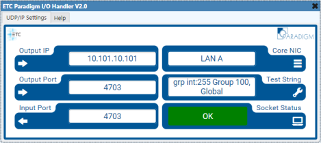
Runtime Elements UDP/IP (preferred)
- Output IP
- IP address of the Paradigm processor
- 10.101.10.101 (default)
- Output Port
- Paradigm UDP port to send commands to
- 4703 (default)
- Input Port
- Q-SYS UDP to receive status updates on
- 4703 (default)
- Core NIC
- Select LAN A or LAN B depending on the capabilities of your core
- Not Selected (default)
- Test String
- Send/receive to/from Paradigm to verify bidirectional communication is occurring
- Send ? to Paradigm to verify bidirectional communication
- Paradigm will send a reply with all PSAP commands within the API
- Socket Status (read only)
- Indicates OK when the proper ports is selected and operating properly
- Indicates when in emulation mode
- Indicates when a fault has occurred
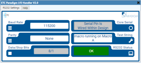
Runtime Elements RS232
- Baud Rate
- Choices
- 9600 (default)
- 19200
- 38400
- 57600
- 115200
- Choices
- Parity
- Choices
- None (default)
- Even
- Odd
- Choices
- Data/Stop bits (read only)
- 8/1
- Core Serial (read only)
- Indicates if the serial port is properly wired within the schematic
- See Test String
- RS232 Status (read only)
- Indicates OK when the desired serial port is properly wired within the schematic
- Indicates when in emulation mode
- Indicates when a fault has occurred
Designtime Properties
- Communication Type
- Select UDP/IP (preferred) or RS232
- If RS232 communication is required for your project it is reccommended to set the baud rate to 115.2Kbaud for optimal performance
- End of Message Char
- Carriage return end of message byte is Paradigm's default
- Choices
- CR (default)
- CR+LF
- LF
- Plugin Group ID
- Assign all control plugins and the I/O Handler that need to communicate with each other to the same ID
- The Plugin Group ID makes it possible to control many independent Paradigm systems from a single Q-SYS design
- All plugins with the same group ID will play in their own control "sandbox" together
- Most projects will only require the use of a single Plugin Group ID
- Choices
- 1-65535 (default 1)
- I/O Max. Retries
- Not used when setup for RS232
- Number of times the core will try to open the UDP port after a reboot or design load
- The core will stop trying to open the UDP port once the maximum retries set within properties has been met or the UDP opens
- Utilize this feature if the Ethernet switch takes longer to boot than the Q-SYS core to avoid having to reboot the core
- Choices
- 0-100 retries (default 0)
- I/O Retry Interval (secs)
- Not used when setup for RS232
- Delay time in between retries to open the UDP port
- Choices
- 1-300 seconds (default 60)
- Print to Event Log
- Sends received/transmitted data details to the core's webserver event log
- After troubleshooting be sure to set this property to NO and reload the design to the core
- Choices
- No (default)
- Yes
- Show Debug
- Exposes or hides the plugin's debug window
- No (default)
- Yes (exposes Debug Print property)
- Exposes or hides the plugin's debug window
- Debug Print
- When Show Debug is set to Yes this property is visible
- After troubleshooting be sure to set this property to NO and reload the design to the core
- Choices
- Show All(default)
- Logs all of the below debug messages within the plugin's debug window
- Show None
- Turns off all debug logging
- Show Errors
- Logs errors the plugin produces
- Show Function Calls
- Logs when functions within the plugin are called
- Show Rx
- Logs received status updates from Paradigm
- Show Rx/Tx
- Logs sent/received commands/update to/from Paradigm
- Show Tx
- Logs sent commands to Paradigm
- Show All(default)
Control Pins
Preset Control Setup
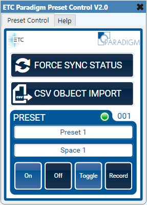
Runtime Elements
- Force Sync Status
- When pressed it will poll the Paradigm system for the status of the objects within this plugin
- The plugin will update UI elements to reflect the proper on/off states of the objects they control within Paradigm based on the status Paradigm returns
- CSV Object Import
- Allows plugin data to be imported via CSV file for fast setup
- CSV files must reside on the core
- Non-UTF CSV format is supported
- Here are examples of how to format the CSV files
- Preset Name
- Enter the Paradigm preset name to control (observe case and spelling)
- Space Name
- Enter the Paradigm space name to control the object within (observe case and spelling)
- LED Indicator
- Indicates the on/off status of the preset
- If the altered state is enabled within this plugin the indicator will go to the altered state when the preset goes altered
- The altered state is when a preset is not fully on nor fully off but is still playing back a portion of its recorded look
- On
- Activates the preset
- Off
- Deactivates the preset
- Toggle
- Toggles the preset between the activated and deactivated states
- Record
- Once this button is pressed the levels of the preset will be recorded
Designtime Properties
- Preset Quantity
- Choices
- 1-100 (default 1)
- Choices
- See Plugin Group ID
- See End of Message Char
- Sync Time Delay
- Visible when Sync Status on Boot is set to Yes
- The polling interval in seconds the plugin uses to retrieve object status from Paradigm
- Increase the polling time if status is not properly updating on boot or when forcing sync status
- Choices
- 0-60 seconds (default staggered)
- Sync Status on Boot
- Exposes or hides the Sync Time Delay property
- Polls Paradigm for status on boot when set to yes
- Choices
- Yes (default)
- No
- Choices
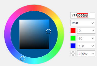
- On Button/LED State
- When the associated Paradigm object is on/active the control will turn this color
- This overrides the colors set within the UCI editor
- Enter the color by using the 6 character hex format omitting the alpha channel byte (e.g. #005696)
- Alternatively the color can be set by entering any basic color name supported by Q-SYS (e.g. Red, Blue, Black, etc...)
- Off Button/LED State
- When the associated Paradigm object is off/deactivated the control will turn this color
- Altered Button/LED State
- Exposed when the Enable Altered State property is set to yes
- When the associated Paradigm object is altered the control will turn this color
- Enable Altered State
- Exposes or hides the Altered Button/LED State properties
- Choices
- No (default)
- Yes
- Choices
- Exposes or hides the Altered Button/LED State properties
- See Show Debug
Control Pins
- See Disable
- Preset Name
- Space Name
- Direction
- Input & Output
- Values
- string/text
- Direction
- Preset Off
- Preset On
- Preset Toggle
- Preset Record
- Direction
- Input & Output
- Values
- Trigger/true
- Direction
- Preset Status
- Direction
- Output
- Values
- 0/false
- 1/true
- Direction
- Preset Sync Status
- Direction
- Input
- Values
- Trigger/true
- Direction
Channel/Group Control Setup

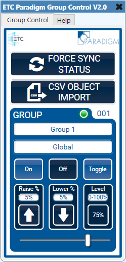
Runtime Elements
- See Force Sync Status
- See CSV Object Import
- Channel/Group Name
- Enter the Paradigm channel/group name to control (observe case and spelling)
- See Space Name
- LED Indicator
- Indicates the on/off status of the channel/group
- On
- Activates the channel/group
- Off
- Deactivates the channel/group
- Toggle
- Toggles the channel/group between the on and off states
- Raise
- Tap or press/hold to raise the channel/group level
- Click the value above the raise button to change the value
- Choices
- 0-100% (default 5%)
- Lower
- Tap or press/hold to lower the channel/group level
- Click the value above the lower button to change the value
- Choices
- 0-100% (default 5%)
- Level Display
- Displays the real time channel/group level in Paradigm
- Click the dropdown above the display to change how the channel/group level is displayed
- Choices
- Percent (default)
- 0-255
- Choices
- Slider
- Linear control of the channel/group level
- Will update position based on channel/group status level updates from Paradigm
- Status level updates from Paradigm are disabled on THIS slider while under manual control and will enable 5 seconds after releasing the slider
Designtime Properties
- Channel/Group Quantity
- Choices
- 1-100 (default 1)
- Choices
- See Plugin Group ID
- See End of Message Char
- See Sync Time Delay
- See Sync Status on Boot
- See On Button/LED State
- See Off Button/LED State
- Raise/Lower Delay
- The amount of time in seconds a user needs to hold the button before the level will repeatedly move
- Choices
- 0-60 seconds (default 1)
- Raise/Lower Interval
- The amount of time in seconds the level is automatically applied while the user is holding the button
- Choices
- 0-60 seconds (default .250)
- See Show Debug
Control Pins
- See Disable
- Channel/Group Name
- Space Name
- Direction
- Input & Output
- Values
- string/text
- Direction
- Channel/Group Level Display
- Direction
- Output
- Values
- 0-100% or 0-255
- Direction
- Channel/Group Raise Intensity
- Channel/Group Lower Intensity
- Direction
- Input & Output
- Values
- Momentary Held/1/true
- Momentary Release/0/false
- Direction
- Channel/Group Raise Value
- Channel/Group Lower Value
- Direction
- Input & Output
- Values
- 0-100%
- Direction
- Channel/Group Off
- Channel/Group On
- Channel/Group Toggle
- Direction
- Input & Output
- Values
- Trigger/true
- Direction
- Channel/Group Slider Level
- Direction
- Input & Output
- Values
- 0-255
- Direction
- Channel/Group Status
- Direction
- Output
- Values
- 0/false
- 1/true
- Direction
- Channel/Group Sync Status
- Direction
- Input
- Values
- Trigger/true
- Direction
Macro Control Setup
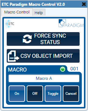
Runtime Elements
- See Force Sync Status
- See CSV Object Import
- Macro Name
- Enter the Paradigm macro name to control (observe case and spelling)
- LED Indicator
- Indicates the running-on, on, running-off and off status of the macro
- On
- Plays macro on steps
- Off
- Plays macro off steps
- Toggle
- Toggles the macro between playing on and off steps
- Cancel
- On or Off step execution is canceled
- Once canceled, the macro will either go to the full on or full off state depending on which steps were previously executing
Designtime Properties
- Macro Quantity
- Choices
- 1-100 (default 1)
- Choices
- See Plugin Group ID
- See End of Message Char
- See Sync Time Delay
- See Sync Status on Boot
- See On Button/LED State
- Running-On Button/LED State
- When the associated macro is actively executing macro on steps the control will turn this color
- See Off Button/LED State
- Running-Off Button/LED State
- When the associated macro is actively executing macro off steps the control will turn this color
- See Show Debug
Control Pins
- See Disable
- Macro Name
- Direction
- Input & Output
- Values
- string/text
- Direction
- Macro Off
- Macro On
- Macro Toggle
- Macro Cancel
- Direction
- Input & Output
- Values
- Trigger/true
- Direction
- Macro Status
- Direction
- Output
- Values
- 0/false
- 1/true
- Direction
- Macro Sync Status
- Direction
- Input
- Values
- Trigger/true
- Direction
Wall Control Setup
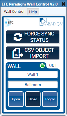
Runtime Elements
- See Force Sync Status
- See CSV Object Import
- Wall Name
- Enter the Paradigm wall name to control (observe case and spelling)
- LED Indicator
- Indicates the open and closed state of the wall
- Open
- Opens the wall
- Close
- Closes the wall
- Toggle
- Toggles the wall between open and closed
Designtime Properties
- Wall Quantity
- Choices
- 1-100 (default 1)
- Choices
- See Plugin Group ID
- See End of Message Char
- See Sync Time Delay
- See Sync Status on Boot
- Opened Button/LED State
- When the associated wall is open the control will turn this color
- Closed Button/LED State
- When the associated wall is closed the control will turn this color
- See Show Debug
Control Pins
- See Disable
- Wall Name
- Space Name
- Direction
- Input & Output
- Values
- string/text
- Direction
- Wall Close
- Wall Open
- Wall Toggle
- Direction
- Input & Output
- Values
- Trigger/true
- Direction
- Wall Status
- Direction
- Output
- Values
- 0/false
- 1/true
- Direction
- Wall Sync Status
- Direction
- Input
- Values
- Trigger/true
- Direction