Network Definitions
This article provides basic definitions of terms, phrases, and concepts used in networking. As with most support articles, the listed definitions will be added to or modified over time.
This article does not go into full details about every word, phrase, or concept. If you would like to learn more about networking definitions in general, the Internet has lots of in-depth network support articles and we encourage you to use your search engine of choice to explore these topics. If you would like to learn more about a specific word, phase, or concept and how it specifically relates to an ETC control system, please feel free to reach out to ETC Applications Engineering or ETC Technical Support.
Terms
10/100/1000BASE-T
Common data-rate transmission speeds expressed as megabits per second (Mbps or Mb/s) used in Ethernet-based networks. 100 Mbps has been the most common for a number of years, although 1000 Mbps is becoming much more common, and is also frequently expressed as 1 Gbps (Gigabit per second). 1 Mbps is equal to ~125 kilobytes per second (KB/s) bandwidth, so while approximately 125 megabytes per second (MB/s) is theoretically possible on a 1000 Mbps connection, observed bandwidth on any connection may be slightly less due to processing overhead and other capabilities of the networking hardware.
2.5/5/10GBASE-T
Common data-rate transmission speeds expressed as gigabit per second (Gbps or Gb/s) used in Ethernet-based networks. Currently they're not as common in the consumer market
2.4GHz
The frequency band in the radio spectrum used by many Wi-Fi devices. Shared with Bluetooth, Zigbee, and many other wireless technologies. Has a potentially longer range than 5GHz Wi-Fi and greater compatibility with older devices, but has lower potential bandwidth.
5.0GHz
A newer frequency band used by Wi-Fi devices. Has a higher bandwidth than 2.4GHz and is less likely to interfere with other common wireless technologies, but has a potentially shorter range. Many modern routers and access points can broadcast both 2.4GHz and 5.0GHz Wi-Fi using two different SSIDs, and internally bridge the two networks.
Access Control Entry
See Access Control List. An Access Control Entry (ACE) is an individual line or condition in an ACL. For example, an ACE condition may block port 5568, which is used by sACN lighting-level packets. That would be one line/condition in the ACL and is considered an ACE.
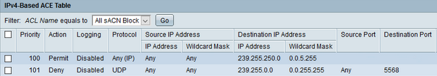
Access Control List
An Access Control List (ACL) is a feature in network switch hardware. This feature allows the switch to block or allow network traffic based on specific conditions. The conditions are input by a technician using the network switch's Console Port or web user interface. This ACL is applied on a port-by-port basis (physical network ports on the hardware). Think of an ACL as a traffic monitor that inspects every network packet entering or exiting a network port. The packet(s) will either be blocked or permitted based on the conditions in the ACL. Depending on the capabilities of the network switch, the ACL may be applied to incoming traffic, outgoing traffic, or both. The most common ACL used in ETC networks is to block sACN lighting levels.
In this example, two different areas of a building each have a lighting controller that both use sACN universe 1. Both areas of the building exist on the same lighting network but are on different lighting switches. It is then desirable to block sACN traffic between the network switches so that area A doesn't accidentally control area B.


For more information on how to configure ACLs in Cisco network switches, see this article.
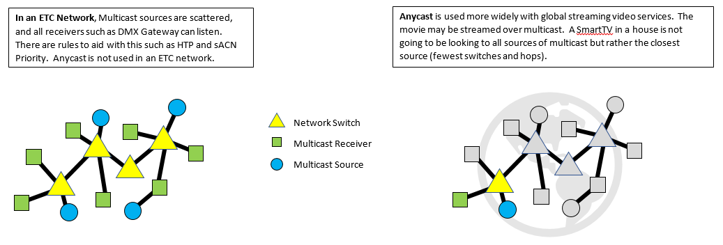
Anycast
Used to describe the transmission of data over a network. Read the Multicast definition first to better understand the concept of Anycast. First, there are no ETC products that support Anycast at this time. Anycast is when a network device (receiver for multicast network traffic) sources its multicast network traffic from the closest logical source on the network when multiple sources are present. A good analogy would be to think of Internet video streaming services. If the streaming service has let's say 5 locations around the country that all host a video that you want to watch, Anycast would tell the network switches (network infrastructure) that your receiver (home PC or smart TV or phone) would stream the video from the closest logical host (source). The video would be streamed over multicast (only those who ask to get that information will get it). Once again, this is not supported by ETC hardware. In a lighting network, if more than one source of sACN exists, the receivers, DMX gateways for example, would want to receive all sACN sources and decide for itself which one "wins" using HTP (Highest Takes Precedence) and sACN Priority values. Hence, lighting receivers want to listen to all multicast sources.
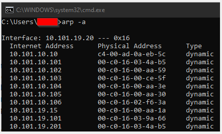
arp -a
This is a Command Prompt command. The purpose of arp -a is to return or print a list of IP Addresses and MAC Addresses that this computer has communicated with. This is an excellent way to gather a list of MAC Addresses for the ETC networked hardware on a site. The easiest way for your computer to interact with networked hardware is to run Concert or other product specific software such as LightDesigner or EchoAccess. The simplest way is to simply ping an IP Address and arp -a will return the MAC Address. In the screenshot below, the PC has an IP Address of 10.101.19.20 and launched LightDesigner. The returned list shows a PCCS at 10.101.10.10 and the remaining are all PACPs.
BACnet
BACnet (Building Automation and Control Networks) is a protocol created in 1995 as ASHRAE-135, used to control/monitor multiple systems within a facility, including HVAC, fire/life safety systems, access control, energy utility/buliding integration, wireless communications, and lighting systems. BACnet supports multiple physical data link technologies.
BACnet/IP
One of the data link technologies utilized by BACnet, and the only one supported by ETC products, including the Paradigm Central Control Server (P-CCS), Echo BACnet Interface (EBI), Mosaic Show Controller (MSC), and EchoFlex CAN2GO BACnet Gateway.
BBMD
BACnet Broadcast Management Device. Receives BACnet broadcast messages on one IP subnet, and forwards then to another subnet. Used as a special type of router to bridge BACnet messages across two networks.
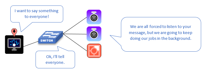
Broadcast
Used to describe the transmission of data over a network. Broadcast is when network information from the source (transmitter) is sent to all devices on the network. Think of this like a flyer in the mail that gets sent to every home. This forces all devices to receive the broadcast information and do one of two things; either act on it (do an action) or ignore it (throw it in the invisible trash can). Broadcast storms often refer to instances when all the data on the network is being broadcast and forcing devices to spend all their time throwing away messages rather than doing their normal computing tasks. In the mail example with the flyers, its like spending all of your time throwing away flyers you are not interested in. This can result in slower response from devices or even device reboots.
Category Cables (Ethernet)
Over time, Ethernet-based networks have used different Category cables, expressed as "Cat#". Each variant has characteristics that (typically) allow for higher frequency transmission and bandwidth speeds over specific lengths of cable. Since 2001, Cat5e has been the most common, while Cat6 and Cat6a have become more frequent, as they are backwards compatible with Cat5/5e. A chart of some relevant information is found below:
| Cable Type | Max Frequency | Supported Transfer Speeds | Max Length |
|---|---|---|---|
| Cat5 | 100 MHz | 10BASE-T 100BASE-TX 1000BASE-T 2.5BASE-T |
328 ft / 100 meters |
| Cat5e | 100 MHz | 10BASE-T 100BASE-TX 1000BASE-T 2.5GBASE-T |
328 ft / 100 meters |
| Cat6 | 250 MHz | 10BASE-T 100BASE-TX 1000BASE-T 2.5GBASE-T 5GBASE-T 10GBASE-T |
328 ft / 100 meters (up to 5GBASE-T) 180 ft / 55 meters (for 10GBASE-T) |
| Cat6a | 500 MHz | 10BASE-T 100BASE-TX 1000BASE-T 2.5GBASE-T 5GBASE-T 10GBASE-T |
328 ft / 100 meters for all speeds |
Command Line Interface
CLI for short. A type of interface, often used to configure a device such as a network switch, in which commands are input via text. Examples include Command Prompt or PowerShell on Windows, Terminal on macOS, Bash on many Linux distributions, and the command line in Eos. A command line interface often contains the same or more options for configuration of a device than a graphical user interface (GUI) such as a webUI for a network switch. CLI commands use specific syntax and it is recommended to refer to a manual when first learning to use it.
Command Prompt
A command line interface available on Windows computers. The commands mentioned in this article reference those on a Windows PC. Commands for other operating systems (or other CLIs such as PowerShell) will vary.
The Command Prompt allows the user to enter commands written in specific syntax in order to return information about your computer or the network the computer is connected to. Command Prompt examples such as arp -a and ping are also defined in this article. To access the Command Prompt, press the Windows button and go to Run (Windows button + R shortcut). Next type in cmd and press Enter. This will launch a new window with a black background and a blinking cursor.
Console Port
A port used to configure a network switch. A typical managed network switch will have multiple methods by which to configure its settings. The most common is a web user interface, accessed by entering the switch's IP address into a Web browser. Managed switches may also offer a specific physical port on the switch hardware for switch configuration. On Cisco SG350 network switches, for example, the console port is an RJ45 port on the rear of the hardware. This port does not carry Ethernet communication, rather, it uses RS232 over an RJ45 to D-SUB 9 serial connector to establish a CLI between a computer and the network switch for configuration.
Core Switch
A switch used in a large Ethernet network to connect many switches to the same physical network.
DHCP
Dynamic Host Configuration Protocol. Used to distribute IPV4 addresses to devices on a network. DHCP requires that a server is present on the network and that a device is set up to configure its IP address automatically. When a device (known as a DHCP Client) needs an IP address, it can request one from the DHCP server, which will then lease an address to the client. The lease will expire after a period of time configured by the network administrator. Since a limited number of addresses can be used on a local network at a time, a network which expects many clients will likely have a shorter DHCP lease period. For example, in coffee shops, when connecting to wifi, the coffee shop will assign your device an IP address and will likely expire within 24 hours. At a home or office, the same process may include a lease that is good for a longer period of time like a month or a year.
In lighting systems, depending on the venue the network infrastructure, static IP addresses are preferred for permanently installed networked devices while the addresses for temporary devices such as DMX gateways or mobile devices running console applications are more frequently dynamic.
There can only be one DHCP server on a network but there can be many clients. If more than one server exists, unexpected results may occur. Note that the server should also be configured to lease IP addresses that are in the same IP subnet that is in-use by other devices on the network, otherwise network communication will not be possible.
ETC devices that can be DHCP servers include: Eos Family Consoles, Cobalt Family Consoles, High-End Systems Hog Family Consoles, Conductor.
DNS
Domain Name Service. All IP communication happens between unique IP addresses, but these are not easy to remember, and an IP address may change without a user's knowledge. When a client (such as a Web browser) wants to connect to a server (such as the ETC website), it asks a DNS server to translate a human-readable domain (such as etcconnect.com) to an IP address that it can then communicate with.
While dedicated lighting networks often do not have a DNS server, many devices require a DNS server to be defined before they will allow network traffic of any kind. There are many public DNS server addresses that can be used as a placeholder in these cases.
EtherChannel
A feature in Cisco switches which allows multiple physical network ports between two switches to be treated as a single logical link, sharing their bandwidth. For example, 2 ports at 1Gbps could be linked together using EtherChannel to create a single link with 2Gbps total bandwidth.
Generically, this type of feature is called Link Aggregation.
Fiber Optic Cable
A type of Ethernet cable which sends pulses of light down fibers of glass for communication, as opposed to the electric voltages through copper used by traditional low voltage wiring. Has significantly higher potential bandwidth than copper cable, and can have significantly longer runs than Category cable, but is more expensive, more delicate, and requires specialized tools to install and maintain.
Fiber (Short Haul)
A fiber run generally under 10Km in length. Used in local networks. The light in a short-haul fiber run can be generated using low powered lasers or LED emitters.
Fiber (Long Haul)
A fiber run over 10Km in length to create large-scale communications infrastructure. Requires specialized cable, signal amplifiers and repeaters, and extremely precise lasers to propagate the signal.
Flow Control
Various methods to slow down the flow of data on a given communications link, so that a device that can send a lot of data does not overwhelm a device which cannot support that quantity of data.
GBIC
Gigabit Interface Converter. A piece of hardware which allows different types of cable, such as copper Category cable or multimode / single mode fiber, to connect to a single switch interface. Superseded by the SFP form factor.
HTTP
Hypertext Transfer Protocol. Primarily used by web browsers to access pages on the Internet, this protocol is a method for a client to make requests of a server and for that server to respond to those requests. In ETC products, this is most often used to access device web interfaces, but can also be used by technologies like the Mosaic API.
HTTPS
Hypertext Transfer Protocol(Secure). A revision of HTTP which implements encryption for added security, preventing devices from intercepting traffic between the client and server.
Hops
In a mesh-topology network, the number of times a particular signal is re-sent by a device. To prevent overcongestion, the number of hops a given signal can make in a mesh network is often limited with a TTL value.
IGMP
Internet Group Management Protocol. This protocol is used to establish groups of multicast subscriptions on a network to reduce the bandwidth needs of multicast traffic.
IGMP Querier
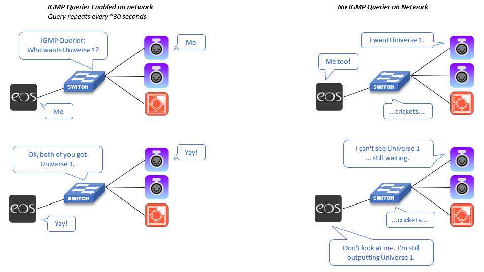
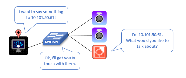
When enabled, a network switch may act as a "querier" to coordinate multicast traffic such as sACN lighting levels. Its job is to send out a "query" at a regular interval to ask all network devices if they are interested in multicast traffic such as sACN universes. A DMX Gateway, for example, will respond to a query with a simple Membership Report packet, instructing the network that it is interested in a universe such as universe 1. Switches that have IGMP snooping enabled between any source of universe 1 and that gateway will forward that universe's data to the DMX gateway port.
Unregistered Multicast is multicast data that has not been accounted for by IGMP.
IGMP Querier Election
Only one active IGMP Querier may be present on a network (or VLAN). The Querier is a feature that can be enabled and disabled on managed switches (depending on make/model). In a multiple network switch system, if Querier is only enabled on one switch, that switch will be the Querier. However, all switches in a network should have the querier enabled, in case the active querier fails. Since there can only be one active querier at a time, a system of switches must have a method to decide which switch will be the active querier at any given time. This process is called Election.
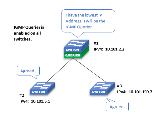
In Cisco switches provided by ETC, the switch with the lowest IP Address will be elected the Querier*. All other switches with Querier enabled will not output Querier messages. In the event the Querier is no longer seen on the network, the next lowest IP Address will take over as Querier and so on.
If the lowest IP Addressed switch is not the desired Querier, it is recommended to change the IP Address of the desired switch so that it is the lowest. In the default ETC network scheme, 10.101.1.1 is the lowest IP address but it is recommended to leave this reserved if a router is needed in the future. 10.101.1.2 would be the next lowest IP address.
It is recommended to make the core switch or the switch closest to the center of the network (fewest hops to all other switches) be the IGMP Querier. This switch should also be easily accessible in the event of failure.
*Other switch manufacturers may implement IGMP Querier Election differently, if it is implemented at all. Multiple managed switches from different manufacturers (such as Cisco and Pathway) on the same network with IGMP Querier enabled may not correctly elect a querier, resulting in unpredictable multicast behavior!
IGMP Snooping
Allows switches to detect multicast groups based on the multicast traffic flowing through them. A switch with IGMP snooping enabled will process IGMP query responses from devices connected to the switch and forward multicast traffic accordingly. A switch without IGMP snooping enabled will treat all multicast traffic as unregistered.
IGMP - Membership Report (Join Group)
The message sent from a multicast receiver when it first connects to a network, when it needs to update which multicast groups it belongs to, or in response to an IGMP query. These messages are detected by switches with IGMP snooping enabled so that they can correctly forward multicast traffic.
A 4-port gateway assigned to sACN universes 1, 2, 3, and 4 will send a membership report when it connects to the network saying that it needs to have those universes forwarded to it--or, in other words, that it is part of the multicast group for those four universes. All switches on the network with IGMP snooping enabled will then work together to ensure that port receives those universes from any source on the network. It will send the same membership report each time it receives a query from the querier. If you reconfigure the gateway to receive sACN universes 2, 3, 4, and 5, it will send a new membership report immediately for those universes, as well as a leave group message for universe 1. The snooping switches will then stop sending universe 1 to that port and begin sending universe 5. The gateway will continue to respond to queries from the querier with the new report.
IGMP - Query Interval
This is the interval of time between General Membership Query packets transmitted by the IGMP Querier on a network. Typically this interval can occur anywhere between 30 seconds to 125 seconds. In order words, every X seconds, the querier sends out a packet asking if anyone is interested in multicast traffic. Note that while there is only ever one IGMP querier active on a network, it is still possible for other network switches to have querier enabled in the event that the designated querier goes offline.
All switches on the same network (that have querier enabled) must have the same query interval timers, or multicast traffic may become unstable if the querier goes offline.
IGMP - Robustness
This is the quantity of General Membership Query packets transmitted at the given Query Interval. Typically this ranges from 1 to 10. As these packets are UDP, high robustness is beneficial as the querier has no way of knowing if a device did not receive a query packet.
IGMP - Leave Group
It is possible for a multicast receiver to notify the querier that it wishes to leave a multicast group. For example, if Port 1 on a DMX Gateway is changed from sACN Universe 1 to sACN Universe 2, the gateway transmits a Leave Group packet notifying the querier (and all snooping switches) that it no longer needs to listen to sACN Universe 1 (239.255.0.1). The switch hardware will then stop forwarding packets from that multicast address to the device (physical network port) that submitted the Leave Group request.
IGMP - General Membership Query
A message sent by the IGMP Querier to determine which multicast groups have any active members. If, for example, a querier sends this message and receives no response for sACN universe 500, the system knows that it does not need to forward traffic for that group or gather any details on its members.
IGMP - Group Specific Membership Query
A message sent by the IGMP Querier to determine if any particular multicast group has active members. For example, if a console starts outputting sACN universe 500, the querier may send this message to determine if any gateways need to receive that universe.
IP
Internet Protocol. This protocol defines how messages are structured and sent between devices on a TCP/IP network.
IP Address
A unique numerical identifier, sometimes colloquially referred to as "an IP," assigned to each logical device on a TCP/IP network. An IPv4 address is 32 bits, almost always represented as 4 octets in decimal form, delineated by periods.
For example, the default IP address for port 1 on an Ion is 10.101.100.101.
IP addresses can be either static or dynamic.
- Static
- set by an arbitrary means, usually set by a manufacturer or user-defined
- Not meant to change, so they can be documented and relied on
- Useful for infrastructural devices such as switches, dimmer racks, and processors
- Dynamic
- Set by an application on the network such as a DHCP or BootP server
- Can change at any time
- Useful for devices we don't need to remember the IP of such as gateways and network fixtures
IPv6 has significantly larger IP addresses that are notated differently, but as of 2026, all ETC devices exclusively implement IPv4.
All devices on a LAN must have a unique IP address, or messages cannot be transmitted correctly, potentially between any device on the network. A common troubleshooting step when diagnosing network communications issues is to ensure there are no duplicate IP addresses on the network.
IP Subnet
The devices on an IP network that may communicate with each other via unicast communication. Devices which are not in the same subnet will fail to communicate directly. The subnet for each device is defined by its subnet mask or prefix length and its own IP address.
Subnet Mask
A 32-bit value, represented as four octets delineated by periods, which defines a device's subnet.
A subnet mask defines which bits of two addresses must match between two network interfaces' IP addresses in order to establish unicast communications. When comparing the two IP addresses, if a bit in the subnet mask has the value of 1, both the sending and receiving device must have the same value for that bit, either 1 or 0. If the bit in the subnet mask is 0, the corresponding bit in the IP addresses does not need to match. Subnet masks are generally a sequence of a certain number of 1s followed by 0s for the rest of the value, so it is also called a "prefix length."
That's a lot of low-level computing jargon, but in practical terms it is fairly simple. For most networks, a subnet mask will consist of either one, two, or three 255s in a row:
255.0.0.0 (or prefix length 8, represented as /8)
255.255.0.0 (/16)
255.255.255.0 (/24)
Four 255s would not be valid, because two devices would need the same IP to communicate, but two devices on the same network may not share an IP address. All 0s is not invalid, but is extremely unusual for LANs.
When comparing the four-octet IP address of two devices, if their subnet mask has a 255, that octet must have the same value, and if it has a 0, the octet may have any value.
If you want to use an Ion XE as a client for an Apex, the Ion must be on the same physical network as the Apex, and it must be within the same subnet. The default IPs for port 1 of both devices are already set that way, so we can use them as an example.
Our Ion XE's port 1 IP address is 10.101.100.20.
Our Apex's port 1 IP address is 10.101.191.101.
Both devices have a subnet mask of 255.255.0.0. This means that the first two octets must match for the devices to communicate, and because both IPs start with 10.101, they are in the same subnet and can establish unicast communications.
If you changed the Ion XE's port 1 subnet mask to 255.255.255.0 or changed its IP address to 192.168.100.20, the ports would no longer be in the same subnet and would fail to communicate.
IP Gateway
When a device wants to send an IP message to another device that is not within its own LAN, it sends the message to a gateway, which will pass (or route) that message along to another LAN or gateway to get it closer to its final destination. In the case of Internet traffic, gateways are the devices that are networked together across the world, routing messages in a mesh topology to get them to where they need to go.
The default gateway is the IP address a network interface will (unless otherwise specified by the application) send packets to which have a destination outside of its subnet.
As lighting networks are generally not connected to the Internet, most do not have a gateway, though complex and specialized systems may have routed networks that utilize multiple LANs to manage traffic. Some devices and applications require a default gateway IP to be defined even if it will not be used.
ipconfig -all
Used in the Windows Command Prompt. Displays all IP settings, including DHCP lease times, DNS servers, etc of each network interface on your PC.
"ipconfig" without the "-all" flag will display only the IP address, Subnet Mask, and Default Gateway for currently active ports.
IPv4
The original standardization of the Internet Protocol, introduced in 1980.
IPv6
The most recent Internet Protocol standard, introduced in 1995 and ratified in 2017. Improves on the IPV4 standard in many ways, most notably by increasing from a 32-bit IP address to a 128-bit IP address, to account for the number of devices on the Internet which require unique addresses. As of 2026, it is generally used in the devices which make up the infrastructure of the Internet, but end-user-facing devices are beginning to implement it.
Jumbo Frames
Ethernet messages, called frames, are limited by the Ethernet standard to 1500 bytes. A Jumbo Frame is one which exceeds that limit, and must be supported by the device on both sides of an Ethernet connection to be transmitted.
LAG
Link Aggregation Group. The group of physical ports used to create a single logical port via a Link Aggregation method such as Cisco's EtherChannel.
LAN
Local Area Network. A logical network made up of directly connected devices. Can be connected to other networks (a Wide Area Network or WAN) using a gateway.
In your home, the various network-connected devices in your home, such as your computer, phone, and smart fridge make up a LAN. The WAN they may connect to is the Internet, via the router or modem which acts as the gateway. If the WAN connection is disrupted, the devices on the LAN can still communicate with each other, so your phone can still see what is in your fridge, but your fridge cannot send an order for milk to the grocery store over the Internet.
MAC Address
A Media Access Control address is a unique numerical identifier for every physical network interface. It is represented as six octets in hexadecimal delineated by colons. Unlike IP addresses, MAC addresses do not change.
Managed Switch
Used to describe a network switch that is capable of having its settings or configuration altered using a web interface or Command Line Interface. Unmanaged switches will not have such an interface from which to alter its properties. Managed switches typically allow users to edit common features such as VLAN assignments on each port, Spanning Tree options for each port, and IGMP options for the switch. It is often advantageous to use a managed switch in a lighting network as opposed to an Unmanaged switch so that these properties can be altered to suit the needs of the devices living on the network. However a managed switch that is improperly configured can have undesired consequences for the devices on the network. It is important to understand what the network requirements are for devices living on a managed switch. For ETC provided network switches, visit this link for configuration guides. As always, feel free to contact ETC Applications Engineering for any questions about managed switch settings for ETC lighting networks.
MFA
Multi-Factor Authentication refers to any method which proves a user's identity using more than one piece of information, or "factor." A traditional user name and password has only one factor, the password, to prove that a user is who they say they are. An MFA login system may use a password as well as, for example, some proof that a user has an approved mobile device to make it more difficult to falsify the user's identity.
Multicast
One of several methods of transmitting data on a network.
Multicast traffic is sent to multiple devices on a network, but not to every device. For example, sACN is often sent by lighting controllers via multicast. If a controller sends data on Universe 1, only DMX Gateways programmed to output Universe 1 will receive those levels. DMX Gateways outputting Universe 2 would not receive those levels (unless it is a multiple-port gateway outputting both universes).
In a TCP/IP network, multicast traffic does not require the source and destination devices to be in the same IP subnet.
On a managed switch, IGMP determines which ports receive multicast traffic, reducing the bandwidth used on any given network link. On an unmanaged switch, multicast traffic is broadcast to all ports, but receiving devices determine whether to act on it.
Any given type of multicast traffic, such as sACN, may have more than one source on a network. It is valid for two controllers, such as a lighting console and an architectural controller, to transmit data to a single DMX Gateway. A typical ETC network will have multiple simultaneous sources of multicast traffic.
Network Diameter
In computer networking, a network's diameter is the longest distance (as in the number of hops, not the distance in space) between two nodes.
Network Storm / Broadcast Storm
A condition in which excessive broadcast traffic on a network overwhelms network hardware. Often caused by a network loop: 2 ports on a switch connected to each other, each infinitely rebroadcasting the same packets they are sending and receiving. Network storms can be mitigated either by careful infrastructure planning or by technologies such as Spanning Tree Protocol.
Network Topology
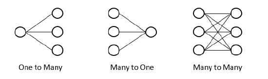
Topology refers to the physical layout of computer networks of any kind. There are several topologies with their own applications, advantages, and disadvantages. For the purposes of this article, the word "node" generally means a network switch, but these topologies can be used to describe any form of networked communication, from DMX, to wireless systems, to analog telephone networks.
Daisy Chain Topology

In a daisy chain topology, each node connects to both the next and previous node in a contiguous line.
This topology works well for DMX, because each node is connected passively to the data line. This means that if the electronics of single device in the chain fail, the system as a whole remains functional.
Since Ethernet networking cannot be passive, a daisy chain topology with switches is not recommended, as each node is a potential failure point for the entire network.
Mesh Topology

A topology in which all nodes on a network may be connected to multiple other nodes. In a mesh topology, there can be multiple (and sometimes many) valid paths for data to take to get from one point to another in the network. As a result, when one node can no longer pass data, it is still possible for data to pass through the network normally. The more connections in the network, the more resilient the network is to individual node failures. However, as the number of connections between nodes increases, the system becomes more complex. Depending on the type of communication being transferred across the network, this complexity may have consequences.
In Ethernet networking, a mesh network is only possible when there are rules for how data gets from one point to another. Without these rules, a network storm would prevent communications between any devices. Spanning Tree Protocol allows for a mesh network without a network storm.
Ring / Loop Topology

A ring or loop topology is similar to a daisy chain, as each node in the network is connected to the next and previous node in line. In a ring, the first and last nodes are also connected. If a single node on the network can no longer pass data, the network is still functional, but further failures are likely to quickly cause problems. However, a ring is simpler than a mesh, so its maintenance may not be as resource-intensive.
In Ethernet networking, a ring is easier to set up than a mesh, but it still requires STP to prevent network storms. All switches in a ring network will likely share bandwidth fairly equally.
Star Topology

Also called "hub and spoke." In a star topology, there is one node which all other nodes connect to and through which all data flows. Any number of nodes on the outside of the star can fail without disrupting communication between other nodes on the network, but if the node that all other nodes are connected to fails, the entire network fails.
In Ethernet networking, most small networks use star topology, with a switch at the center and other devices plugged into it. Networks of up to three switches can be considered star topology. In larger networks, the switch at the center of the star is a core switch that can handle much more traffic than the switches at the outside of the network.
NIC
Network Interface Controller is the physical hardware that connects a device to a network through either a wired Ethernet cable, or wirelessly to a router or WAP (Wireless Access Point). Most modern devices have the NIC directly hardwired onto a motherboard or expansion card (PCI or PCI-E), but are also commonly found as external adapters via USB or Thunderbolt.
NTP
Network Time Protocol. A standard for synchronizing time between multiple computers on an IP network.
Octet
8 bits of data. Often referred to as a byte, but because "byte" did not always exclusively refer to 8 bits, "octet" is used when describing network addresses for the sake of specificity.
OSC
Open Sound Control. A protocol that defines the structure of messages that can be sent between multimedia devices. Often used to send commands between different types of entertainment control software, which may have no native interoperability, such as between Qlab and Eos, or to allow a user to create a bespoke interface to a piece of software. That interface could be as simple as a custom set of encoders on a tablet, or as complex as a system that detects the position of bodies in a space to dynamically adjust the lighting around them.
PIM
coming soon (Protocol Independent Multicast)
PIM Dense Mode
coming soon
PIM Sparse Mode
coming soon
Ping
A command, implemented in the CLIs of most operating systems, which sends one or more IP "echo packets" to a given device and reports the reply. Any device that supports IP must reply to an echo packet, so a ping command can be used to verify basic, bidirectional, unicast connectivity between any two devices.
A ping command is typically structured ping {ip address}(e.g. ping 10.101.100.101), and depending on the CLI in use, may be modified for different behaviors to fit different troubleshooting needs. For example, the Windows Command Prompt ping command will, by default, send four packets and report whether they were successfully replied to or if any errors occurred.
Note that because Ping is a unicast communication method, when troubleshooting a device on a local area network such as an isolated lighting network, the sending device and the replying device must be on the same IP subnet.
Ping -t
In the Windows Command Prompt, the -t flag tells the utility to repeatedly send packets and report their replies until the user stops the command. This is useful for determining whether there are intermittent issues, such as a switch port or a flaky cable going in and out. A -t ping command is formatted:
ping 10.101.100.101 -t
Private / Public IP Address
Every physical NIC on a given IP network has its own IP address. When a LAN is exposed to the Internet, these devices should not have their IP addresses--called Private IP addresses--exposed. The router between the LAN and the Internet will assign IP addresses to each device that do not match their physical NIC's IP. These are called Public IP addresses.
PoE
Power over Ethernet. A blanket term that refers to many standards for delivering power over an Ethernet line. This eliminates the need to run an additional power line to a device when connected to a device that can supply PoE.
The original PoE standard IEEE 802.3af-2003 allows for up to 15.4W delivered over a single Ethernet line.
PoE+
Defined in the standard IEEE 802.3at-2009. Allows for up to 25.5W of power on a line. A PoE+ port will negotiate with the device at the other end of the cable to determine how much power it needs. Therefore, a device that can be powered via standard PoE will work on a PoE+ port, but a PoE+ device will not work on a standard PoE port.
Proxy ARP
coming soon
QoS
Quality of Service. In computer networking, QoS refers to various methods of prioritizing data based on its application. For example, a router implementing QoS may prioritize streaming data, such as live video requiring high bandwidth and low latency, over less urgent data, such as standard Web traffic.
RJ11
A Registered Jack is a connection standard used in telecommunications that defines the physical connector and wiring configuration to connect two devices. RJ11, used for telephone connections, has a 6-position, 2-conductor connector. Colloquially, "RJ11" may refer to a 6-position connector populated with up to 6 conductors.
RJ45
"RJ45" refers to a connector with 8 positions and 8 conductors, also known as an 8P8C connector. These connectors are commonly terminated to category cable for Ethernet communications. Ethernet wiring using these connectors is defined by the ANSI/TIA-568 standard.
.jpg?revision=1&size=bestfit&width=159&height=160)
sACN
Streaming Architecture for Control Networks (a subset of the full ACN protocol) is a method for transmitting DMX levels over an IP network. (Note that sACN is distinct from and incompatible with DMX over CatV.) First approved by the Entertainment Services and Technology Association (ESTA) in 2009, it is currently defined by the ANSI E1.31-2018 standard.
sACN is transmitted by a source, such as a lighting console or architectural processor, over a TCP/IP network. Each packet contains the data for one universe of levels, or 512 addresses. The packets also contain additional information about which universe they belong to, their source, and their Priority.
An sACN receiver will interpret those packets and, based on its configuration, act on the data. A gateway or node will convert the data to DMX512 data to control other devices. Some devices, such as dimming racks and relay panels, complex multiparameter moving head fixtures, and media servers, are controlled directly via sACN on a network.
sACN is transmitted via UDP. Therefore, just like DMX512, a transmitting device has no inherent awareness of the device it's sending to, or whether the data is being received as expected.
sACN may be transmitted directly to a given IP address via unicast, but is typically sent via multicast. sACN universes range from 1 to 63,999. Each universe, when sent as multicast, is sent to its own multicast address, ranging from 239.255.0.1 to 239.255.249.255.
sACN Discovery
In multicast sACN, a device must subscribe to a multicast address to receive data on that universe. As a result, it will not know which universes are present on a network unless it is already subscribed to those universes.
sACN Discovery addresses this problem by providing a single multicast address (239.255.250.214) to which an sACN source can send "discovery packets," regardless of which universes the source is outputting. These packets contain information about the source and the universes it is outputting, but not the universe data itself. This allows a receiving device or application that supports sACN Discovery to detect which universes are present on a network without manually subscribing to and checking every possible universe.
sACN Priority
Embedded in each packet is a Priority value between 1 and 200 that defines the priority for the entire universe. When multiple sACN sources are present on a network for the same universe, the source with the higher priority "wins" and should be respected by the receiving device. If multiple sources for one universe have the same priority, conflicting address values are usually resolved on a Highest Takes Precedence basis.
The interpretation of sACN priority is determined by the receiving device. Some devices may not correctly respect sACN priority.
An sACN source may also send dedicated sACN Priority packets, otherwise known as Per-Address Priority. These packets allow a source to assign a discrete priority value to every address in a given universe. As with any extended feature of sACN, both the sending and receiving device must support Per-Address Priority for it to function; otherwise, the priority behavior will fall back to the priority value embedded in the universe data.
In an sACN Priority packet, only the "patched" addresses are given priority levels. Unpatched addresses are given a priority of 0. A priority of 0 is still valid, but per the sACN specification, data with priority 0 should be ignored. Some devices may fail to correctly interpret priority 0 data and output it if it is the only source on the network.
sACN Start Code
sACN packets each begin with a 1-byte Start Code, which defines the packet's purpose. In hexadecimal, standard lighting levels packets start with0x00, while per-address priority packets start with 0xDD. Some devices may not correctly interpret start codes other than 0x00, so per-address priority can interfere with lighting levels. If an older or no-name receiving device flickers or flashes when connected to an ETC console, try disabling per-address priority.
SNTP
Simple Network Time Protocol. A simplified version of NTP. Fully compatible with NTP, but lacks certain features, so it is theoretically less accurate but less demanding on the system on which it runs.
Spanning Tree Protocol (STP)
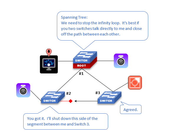
This is a mechanism in network switches that helps to prevent the retransmission of data in a closed Ring / Loop Topology. In this scenario, we will examine a simple system with 3 network switches connected to one another to for a Ring/Loop. Without Spanning Tree, data would flow endlessly around the circle and be re-transmitted indefinitely. Such behavior, also referred to as a Network Storm / Broadcast Storm can easily take down a network (network switches and edge devices such as consoles, controllers, and gateways).
What Spanning Tree does is to block or close off one of the segments so the network is no longer a closed loop. The way it does this is by having one switch be the Root Bridge or center / leader of the switches and all other switches determine how far away they are from the center (Root Bridge), this distance is referred to as Path Cost. Whichever "network segment" has the highest path cost gets blocked and breaks the endless circle. The lowest cost path is the easiest path for traffic so those are left open.
Note: For Cisco switches, individual ports on the network switches that connect to other network switches should have Edge Port disabled. All other ports that host nodes (gateways, controllers, edge devices) should have Edge Port enabled. See Edge Port definition for more details.
STP - BPDU
Bridge Protocol Data Unit is used in Spanning Tree to determine network topology. Spanning Tree is used when a network is set up in a ring or mesh topology. BPDUs are transmitted from each switch to it's neighbor switch to inform them them which physical ports on the switch are in which state (forwarding, listening, blocked, and so on). Think of it like a "Hello" message between neighboring switches. The neighboring switch uses that information to determine what state it should put its ports into and then transmits its own BPDU down the line.
There are multiple pieces of information contained within the BPDU "Hello" packet regarding the switch. Some examples include:
- MAC Address
- IP Address
- Bridge Priority (Switch Priority)
- Network port and speed (physical port)
One of the purposes of the BPDU is to find the best path (or lowest cost path) to the root bridge. Eventually the root bridge will get the BPDU's from its neighboring switch and it will transmit a configuration message on all of its ports. BPDU's are transmitted in moderate frequency of about 1 message every 2 seconds. Note that in a Spanning Tree scenario, at the time of network convergence (when a switch or node is added to the network), ports do not immediately start data transmission immediately. Instead they navigate through many different BPDU states until it is proven that this port does not create a "loop" and is safe, then it will start transmitting data.
STP - BPDU Guard
This is a feature in some Cisco switch models. A BPDU Guard can be applied to physical ports of a network switch. The purpose of a BPDU Guard is to keep Spanning Tree and the network topology predictable. When a port on a network switch has BPDU Guard enabled, the device on the other end cannot influence Spanning Tree on that VLAN/network. If BPDU packets are detected on a network port that has BDPU Guard enabled, then the port is automatically disabled. The port would then have to be manually enabled again using the web interface or command line. This can be done in the Error Recovery Settings area of the network switch.
This is an excellent tool in networks to prevent accidental changes in ring-topology when additional or temporary edge switches are added that may not be part of the permanent loop/ring topology. If BPDU Guard is enabled and a BPDU is detected, the BPDU Handling state for that port will show up as "Guarding" (Blocked State) in the switch webUI. Also the Operational Status of the port will say "Down (BPDU Guard)".
Note that BPDU Guard is used with ports that have PortFast enabled. PortFast still uses STP but allows traffic to flow immediately (port STP is set to "Forwarding State") instead of first waiting for the BPDU's to negotiate the Spanning Tree topology first ("Learning and Listening States", these states are bypassed). If PortFast is enabled and a BPDU packet is detected whilst BPDU Guard is also enabled, then the port immediately gets disabled.
STP - Bridge ID & Bridge Priority
Determines which bridge (or network switch) is elected the Root Bridge in a ring or mesh topology. A Bridge ID consists of the Bridge Priority--a value between 0 and 61400, in increments of 4096--and the port's MAC address. The network switch with the lowest Bridge ID is the root bridge. The Bridge Priority can be edited while the MAC Address cannot. The default Bridge Priority for a Cisco switch is 32768 in a range of 0-61440 (increments of 4096). If all Bridge Priorities are equal (for example, they are left at the defaults of 32768), then the MAC Address is the deciding factor in determining which switch becomes the root bridge. In that case, the switch with the lowest MAC Address becomes the root bridge.
STP - Edge Port
This is a feature in Cisco network switches related to Spanning Tree. Edge Port is the name of the feature in the WebUI, but in the switch configuration file or when using CLI this feature is called PortFast. Edge Port can be set to one of three states per port: Enable, Auto, and Disable. If Enabled, the port is set to a Forwarding State. This means that all traffic is allowed through this port in relationship to the Spanning Tree. This also means that BPDU exchange between switches will not force this port to change state to Blocking, Listening, or Learning. Those other states are what keep a Loop/Ring topology from sending traffic indefinitely ultimately resulting in a Broadcast Storm / Network Storm that could cause undesired behavior (lag, reboot, etc.) in network switches and edge devices (gateways, controllers, consoles).
- If Edge Port is set to Enabled; BPDUs are ignored and traffic will flow around the Loop/Ring indefinitely.
- Use this setting for all ports with Edge Devices connected (gateways, controllers, consoles, anything that is not another network switch).
- CLI Syntax: spanning-tree portfast
- If Edge Port is set to Auto, The link will become active (Forwarding State) after 3 seconds of no BPDUs on the port, thus giving the port time for STP to resolve loops.
- CLI Syntax: spanning-tree portfast auto
- If Edge Port is set to Disabled, BPDUs are respected and STP issues are resolved.
- Use this setting for all ports connected to other network switches.
- CLI Syntax: no spanning-tree portfast
STP - PortFast
(See Edge Port) - This is the Cisco CLI (command line interface) command for using the Edge Port feature. Edge Port is the term used in the Web Interface of a network switch.
STP - Loopback Guard
Sometimes referred to as Loop Guard. This is applied to individual ports on a network switch. The function of a Loopback Guard is to protect network topology in the event that BPDUs are no longer received on a non-Designated Port. Designated Ports on a network switch transmit constant BPDUs to alert the switch on the other end of the segment about the state of network topology.
In an example where fiber is used between switches, there are two connections that make up one segment (at each switch). There is a wire for transmit and a wire for receive which equals a pair of fiber cables. If, for example, the transmit wire was severed but the receive was in-tact, BPDUs would cease to be transmitted from Switch A to Switch B. Switch B would then transition its port state from Alternate to Designated. The Switch B port changes state sas a result of no longer receiving BPDU packets. Associated with BPDU is a max age time. When the max age time expires from the last BPDU the port transitions state (to Designated). When a port becomes Designated, it forwards network traffic. Hence we have now created a network loop. If Loopback Guard was applied, it would place the port that was Alternate into an Inconsistant State which would block all traffic.
In the event that copper was used instead of fiber and only a single copper cable is used between switches (no EtherChannel or LAGs), the Loopback Guard would be less important because it is more likely that the cable as a whole would be severed instead of individual pairs in the cable (example Cat5e). To summarize, if fiber is used between switches in a ring/loop topology, it would be recommended to apply Loopback Guard to all non-designated ports.
STP Path Cost
See also Root Path. The Root Path is determined by the Path Cost. The Root Path is the "lowest cost path" from a given point on a network to the Root Bridge. The Path Cost is evaluated, in part, by the speed of the segment between two switches. The table below outlines Path Costs based on typical network speeds
| Data rate | STP cost | RSTP cost |
| 4 Mbit/s | 250 | 5,000,000 |
| 10 Mbits/s | 100 | 2,000,000 |
| 16 Mbits/s | 62 | 1,250,000 |
| 100 Mbits/s | 19 | 200,000 |
| 1 Gbits/s | 4 | 20,000 |
| 2 Gbits/s | 3 | 10,000 |
| 10 Gbits/s | 2 | 2,000 |
| 100 Gbits/s | N/A | 200 |
| 1 Tbits/s | N/A | 20 |
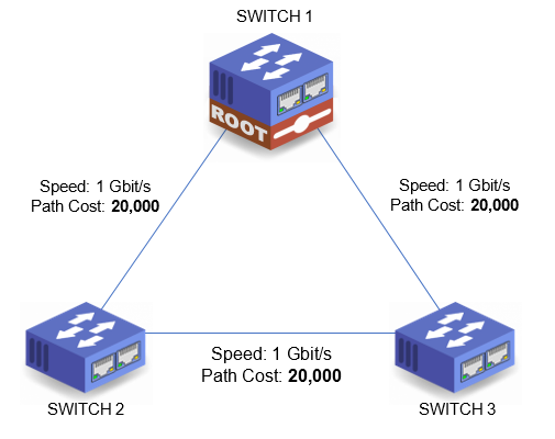
The Path Cost is applied to each segment connecting network switches together. For each segment between a given point in the network and the Root Bridge, the Path Costs are added together. The path with the lowest cost becomes the Root Path.
In the example below, the Path Cost for Switch 2 to get to Switch 1 is 20,000. If Switch 2 were to get to Switch 1 by way of Switch 3, then the Path Cost would be 40,000 (segment between Sw2 and Sw3 (20,000) + segment between Sw3 and Sw1 (20,000) = 40,000). Therefore, as the lowest cost path, the Root Path is directly between Switch 2 and Switch 1.
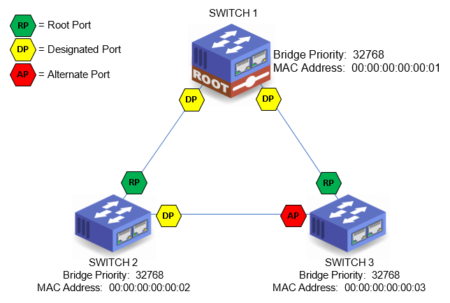
STP Port Role
There are three main port roles: Root, Designated, and Alternate (Blocked). Every active port on a network switch will have a role in Spanning Tree. The individual port roles are explained in further detail below by name. The graphic below shows port roles a simple loop topology.
STP Port Role - Alternate Port
Sometimes called a Blocked Port. The Alternate Port is chosen by looking at the segment and deciding which switch has the lowest Bridge ID. The switch with the lowest Bridge ID will have its end of the segment (port) keep the Designated Port status and the higher Bridge ID will have its end of the segment (port) become an Alternate Port (Blocked Port). This is the where the loop is broken. § This path is automatically disabled by Spanning Tree until such time as the network topology changes (addition or subtraction of a switch or segment) and this port has a lower Path Cost to the Root Bridge.
STP Port Role - Backup Port
In the event that two segments exists between the same two network switches, one port will be designated and the other will be called backup. The backup port will block traffic unless the designated port goes down. If only a single segment exists between two switches that backup port state does not apply.
STP Port Role - Designated Port
A Designated Port exists on at least one end of every segment connecting network switches together. On the Root Bridge, every port connecting to a non-Root network switch is a Designated Port. On non-Root network switches the port that is not the Root Port will become a Designated Port.
STP Port Role - Root Port
A port with the designation "Root Port" implies that this port is the Root Path or "lowest cost path" to the Root Bridge. In a loop topology, there can only be one Root Bridge and only one path (Root Path) to that switch from any given point in the topology. A Root Port is the port on every non-Root network switch that has the lowest Path Cost to the Root Bridge. There can only be one Root Port on every non-Root Switch. Once the Root Bridge, Root Path, and Root Port have been declared, the network knows which segments in the loop to shutdown to prevent infinity loops. Only a port connected to another switch — rather than an edge device such as a DMX gateway — may be designated as a Root Port.
Rapid Spanning Tree
An improvement to the original STP standard, introduced in 2001. Backward compatible with standard STP. Can respond to topology changes significantly faster than legacy STP.
STP - Root Bridge
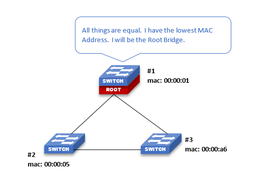
In STP, the Root Bridge is the pre-determined "center" of the switches in a loop. Switches arranged in a loop topology have no inherent center switch, so Root Bridge allows one switch to be elected from which to reference the distance between switches and ultimately shut down the furthest link from it to break the loop and prevent network storms.
In a system where all things are equal between the network switches (cable type, switch port speed, Bridge Priority, et cetera), the network switch with the lowest MAC Address is elected the Root Bridge. A switch may be manually configured as the Root Bridge by altering its Bridge Priority (if supported). Note that physical cable distance or length is not a factor in determining the Root Bridge in most systems.
From the Root Bridge, the Path Cost is determined, and the path to the Root Bridge that has the highest cost will be shut down (the segment between two switches). The paths to the Root Bridge with the lowest costs will remain open for network traffic. If traffic has to travel between multiple switches to get to the Root Bridge, the path with the fewest switches to pass through will remain open (every switch passed through adds a cost to the path).
STP - Root Guard
Root Guard gets assigned to network switch port(s), mostly commonly the ports on the Root Bridge that connect to other switches. The function of the Root Guard is to prevent a Designated Port from becoming a Root Port if a new switch or mis-configured switch converges with the existing network. Root Guard is typically enabled on ports that are facing other switches that are not supposed to be the Root Bridge. In other words Root Guard is applied to ports with switch to switch connections, not for edge devices such as DMX Gateways, Console, Dimmer Racks, et cetera.
STP - Root Path
See also STP Path Cost. The Root Path is the "lowest cost path" from a given point in the network topology to the Root Bridge. The path is predictable if the Root Bridge has been assigned manually and the network topology is known. If the Root Bridge is unknown, then investigation must occur to find the Root Path. This is typically done by accessing an interface for every switch in the network and documenting which port on each switch has Root Port (STP Root Port) designation.
STP States - 1) Blocking / Disregarding State
Upon network convergence, when a port link first comes up, the port is put into a Blocking state. In a Blocking state, the port will listen to BPDU packets from other switches but that is about it. It will not transmit any packets. This allows it to determine the root ID of the Root Bridge and get an idea of what the rest of the network topology looks like. While in this state all other traffic is disregarded. In normal Spanning Tree (not Rapid Spanning Tree RTSP), it can remain in this state for a maximum of 20 seconds. After the Root Bridge and topology are identified, it will move into a Listening State next.
STP States - 2) Listening
After leaving Blocking State, the network port enters Listening State. This state determines if this port is permitted to forward network traffic. It will continue to listen to BPDU packets from other switches but it will now also start transmitting its own BPDU packets. By default this state will have a forwarding delay of 15 seconds. After the delay the port moves to a Learning State.
STP States - 3) Learning
After leaving Listening State, the network port enters Learning State. In this state, the port learns and populates its VLAN and MAC address tables in preparation for forwarding traffic. This is the first state that learns MAC addresses (the only other state that will learn MACs is Forwarding). The port will also remain in this state for 15 seconds (forward delay) before moving to Forwarding State.
STP States - 4) Forwarding
After leaving Learning State, the network port enters Forwarding State. In this state, the port is actively forwarding packets and it considered a part of the network. It continues to send and receive BPDU packets. This is the only state that will forward normal network traffic.
STP States - Disabled State
In this state the packet does not forward any traffic and it does not participate in spanning tree. All packets including BPDUs are ignored. This is the only state in which the port will not send BDPUs but it will continue to receive them (again, it will just ignore them).
STP
Shielded Twisted Pair. A Twisted Pair cable uses two conductors twisted around each other to reduce electromagnetic interference from external sources, thereby increasing the potential bandwidth or reliability of the signal passed through those conductors. An STP cable adds a conductive material around the conductors, which helps absorb additional interference. To be effective, the shield must be connected to ground.
DMX cable, such as Belden 9729, is an STP-type cable. Pin 1 connects the shield to ground, while pins 2 and 3 carry the signal.
Twisted Pair cables without a shield are called Unshielded Twisted Pair, or UTP.
Storm Control
A setting on network switches that watches the quantity of packets traversing a physical network port (interface). If the quantity of packets per second exceeds a specified amount, the interface will dis-allow (block) packets until the quantity of packets decreases below the threshold. At that time, the interface allows traffic to resume (forwarding state). The quantity of packets per second and the hold interval are usually editable settings depending on the switch make and model. Storm Control, again depending on switch make/model, can be applied to unicast, multicast, and broadcast traffic (or combinations of).
Token Ring
Token Ring, developed by IBM, was a competitor to Ethernet. Before network switches, computer networking systems needed to manage data collisions: when more than one device tries to use the same physical hardware at the same time. When Ethernet detects a collision in an unswitched system, it waits for the collision condition to clear and then attempts to retransmit the data. This slows down the network, and the more complex a network is, the slower it gets.
Token Ring circumvented this problem by having each device on the network, connected in a ring topology, share a virtual token that allows a device to send a message only when it has claimed the token. This prevents network collisions at the cost of system complexity.
TTL
Time To Live. Generically, TTL refers to the number of times a given signal can be repeated. This reduces traffic on any mesh network and can prevent a signal from being endlessly repeated.
An IP packet has a TTL value that determines how many times it may be passed from one router to another. Each time a router retransmits the packet, its TTL value decreases by one. If a router receives an IP packet with a TTL of 0, it will not be retransmitted, even if it has not yet reached its destination.
TCP
Transmisson Control Protocol. Along with UDP, one of the main data transmission protocols in the TCP/IP suite of protocols.
TCP is connection-based: two devices make a connection and then transmit data between each other. It is also "reliable," meaning the data transmitted over TCP must be verified and acknowledged by the device receiving it. If the data isn't acknowledged, the transmitting device resends it.
UDP
User Datagram Protocol. Along with TCP, one of the main data transmission protocols in the TCP/IP suite of protocols.
UDP is not connection-based. A transmitting device will send UDP data to a destination on the network without verifying that the destination exists or is ready to receive data. The data is not acknowledged, so the transmitting device does not resend it if it is not received.
Unicast
Used to describe the transmission of data over a network. Unicast is when two devices communicate with each other directly. Example, a lighting system has two controllers (either consoles or architectural controllers). In order from them to communicate with one another and synchronize information, they will send unicast messages directly to one another on the network. This is also commonly used with third party devices that wish to speak to ETC devices over the network. They will exchange unicast or UDP messages back and forth to perform a simple function like activating a cue or preset.
Unmanaged Switch
This is in reference to network switch hardware. An unmanaged switch does not allow for any of its properties, settings, or configuration to be edited. The most common example of an unmanaged switch is a 5-port or 8-port switch commonly found at local brick and mortar stores marketed for residential applications. A scenario in which this is advantageous may be for a small single switch network. If multiple switches are in use, Managed switches are always preferred. An unmanaged switch should not be used in a large network or a network with multiple switches as there is no way to edit common settings such as VLANs, Spanning Tree, or IGMP.
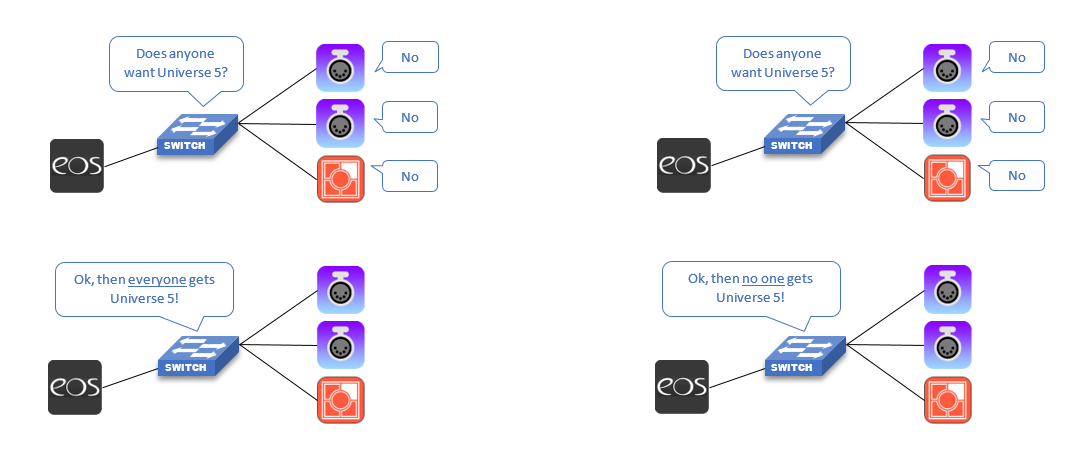
Unregistered Multicast
"If no one asks for it, everyone gets it". If a multicast source like a console is sending out sACN lighting levels or other multicast information and there are no receivers or DMX Gateways asking for that universe, then that universe gets treated like broadcast and those lighting levels get sent to all ports. In small systems this is not an issue. On larger systems, that amount of broadcast can result in undesirable behavior. Example, network products have to discard all packets they receive that don't pertain to them, so a dimmer or relay cabinet has to spent more time discarding packets for universes that it doesn't care about then actually listening to the one or two universes it has patched to itself. Visible side effects of a "broadcast storm" may include sluggish or "laggy" response to level changes and even processor reboots. Using the post office analogy, a broadcast storm is like a mailer or leaflet that just gets sent to everyone, and everyone has to take time to receive the mailer and decide whether to read it (for the coupons) or throw it in the trash/shredder.
Ideally an IGMP Querier will exist on a network that handles the multicast traffic and eliminates this. Unregistered multicast is traditionally set to Forwarding by default meaning that all unregistered multicast gets forwarded to all ports as described above. It is possible to configure network switch ports to instead Filter unregistered multicast. In a filtered environment, if the network port didn't ask for it, it doesn't get it. Cisco switches are able to configure Filter/Forwarding settings on a port by port basis.
Forwarding Example Filtering Example
UTP
Unshielded Twisted Pair. See STP. A twisted pair cable without a shield.
VLAN
Virtual Local Area Network. A collection of ports on one or more managed switches that is treated as a standalone network. This allows groups of devices to have isolated network traffic without requiring multiple switches.
Wake on LAN
A device that supports Wake on LAN (WoL) may be woken from a low-power state via a particular Ethernet message (sometimes called a Magic Packet). This allows networked devices to save power by remotely powering on and shutting down.
WAN
Wide Area Network. See LAN.
Wildcard Mask
This is in reference to Wildcard Masks used in Access Control Lists. Most equate a Wildcard Mask as an inverted Subnet Mask whereas 255.x.y.z means that IPv4 traffic matching the first octet (for example 10.x.y.z) will be allowed/read by the receiving device. In a Wildcard Mask 0.255.255.255 means that the first octet (0) is the match/allowed and anything not 0 is ignored. This is somewhat true but there is more to it than that.
Real world example. sACN traffic. An Access Control List with an entry as follows: Destination IP = 239.255.0.0 and Wildcard Mask of 0.0.255.255 means that any destination IPs of 239.255.0.0 through 239.255.255.255 will be watched. The first two octets are matched and the last two It's up to the programmer to choose whether to permit or deny those packets.
For a more detailed list of Wildcard Ranges related to sACN and Access Control Lists, see this article.