ETC Default Configurations for Pathway Switches provided by ETC
For default configurations of Pathway gateways provided by ETC: Click Here
For detailed information on support of Pathway gateways provided by ETC: Click Here
ETC's Default Switch Configuration Details
General Settings
Device Time Settings
| Property Name | ETC Setting | Pathway Default |
|---|---|---|
| NTP Server | 10.101.50.60 | (blank) |
Network Properties
| Property Name | ETC Setting | Pathway Default |
|---|---|---|
| NTP Server | 10.101.50.60 | (blank) |
| IP Address | 10.101.x.x | 10.30.x.x |
| Subnet Mask | 255.255.0.0 | 255.0.0.0 |
| Gateway | 10.101.1.1 | 10.0.0.1 |
Advanced Features
| Property Name | ETC Setting | Pathway Default |
|---|---|---|
| Rapid Spanning Tree (RSTP) | Enabled | Disabled |
Global VLAN Properties
Advanced Properties
| Property Name | ETC Setting | Pathway Default |
|---|---|---|
| VLAN Support | Enabled | Disabled |
PoE Properties
| Property Name | ETC Setting | Pathway Default |
|---|---|---|
| PoW External Supply Power | 82 W | 0 W |
VLAN Config Tab
VLAN 1 Properties
IGMP
| Property Name | ETC Setting | Pathway Default |
|---|---|---|
| IGMP Querier | Enabled | Disabled |
| IGMP Snooping | Enabled | Disabled |
How to Configure to ETC's Default Configuration
Preparation
A computer (Mac or PC) with Pathscape DMX Software | Pathway Connectivity installed is required for configuring Pathway switches. The computer's network interface must be set to a 10.x.x.x range with a subnet mask of 255.0.0.0
Recommended Computer Network Settings for Configuring Pathway Switches
| IP Address | 10.101.1.101 |
|---|---|
| Subnet Mask | 255.0.0.0 |
| Gateway | 10.101.1.1 |
Add / Log Into / Join Security Domain
If you are starting with all factory defaulted Pathway switches, you will need to create the ETC security domain. If you are reconfiguring a switch previously configured by ETC and have not factory defaulted it, you can join the ETC security domain by using the password "etc". If you are adding a switch previously factory defaulted to a system with existing ETC configured gateways or switches, you can join the device after logging in.
Adding Security Domain
- Navigate to the Security Menu and Choose "New Domain..."

- Enter "etc" in all of the fields

- Click Next
- Select the Device(s) that you want to join the Security Domain (note you have to have a device in order to create a security domain)

- Click Next
- Check the box for "I have saved the Recovery Key" and click Finish

Logging into ETC Security Domain
Devices that have been configured for the ETC security domain will show the lock in amber and the "etc" name in the domain

- Navigate to the Security menu and choose "Log in..."

- Select the "etc" domain from the drop down menu if there is more than one domain present and enter the password "etc"

- Note: The number in parentheses following the domain name is the number of devices online in that security domain.
- Click Finish
- The padlock icon should turn green for devices in the "etc" security domain when successfully logged in

Adding a New Device to the Existing ETC Security Domain
If you have factory defaulted one or more switches but have other gateways or switches still in the ETC domain, you can add the factory defaulted devices to the existing ETC Security Domain.
- Be sure you are logged into the security domain following the process in the previous section (pasword: etc)
- Navigate to the Security menu and choose "Administration..."

- Select the "etc" domain from the drop down menu if there is more than one domain present and enter the password "etc" to log into the Security Domain Admin

- Click {Add} in the "Devices in Domain" section of the Domain Administration Utilities:
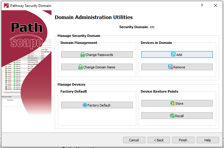
- Select devices that are "Ready to Secure" that you wish to add followed by Add Devices

- Note: the Add Devices to Security Domain dialog will close
- When complete, choose Finish
Configure
Select the switch to be configured in the main window. All of the configuration settings will be changed in the property window.
If the property window is not visible, navigate to the View>Windows>Properties menu to enable it

Change General Settings
- In the Device Time Settings section, set the NTP Server to 10.101.50.60

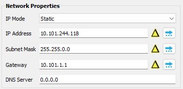
- In the Network Properties section configure the following settings:
- Set the IP Address to a unique address beginning with 10.101.
- Set the Subnet Mask to 255.555.0.0
- Set the Gateway to 10.101.1.1
- In the Advanced Features section, ensure Rapid Spanning Tree (RSTP) is enabled

- In the VLAN Properties section, click the {Global VLAN Properties} button to open the Global VLAN Properties Dialog

- In the Advanced Properties section of the Global VLAN Properties Dialog, select Enabled for VLAN Support

- With VLAN Support Enabled, click {Commit}

- NOTE: If you get the Resolve VLAN Property Conflicts dialog, ensure VLAN Support reads Enabled before clicking {Resolve}

- In the Advanced Properties section of the Global VLAN Properties Dialog, select Enabled for VLAN Support
- In the PoE Properties section, set the PoE External Supply Power to 87 W

Change VLAN Config Properties
- Navigate to the VLAN Config tab

- Expand VLAN 1 and select the device listed below

- In the Properties Window, scroll to IGMP and enable both IGMP Querier and IGMP Snooping

Send Changes
The Transaction Editor is used to send changes to the devices.
If the Transaction Editor window is not visible, navigate to the View>Windows>Transaction Editor menu to enable it

- Click "Send All" in the Transaction Editor to send changes to the devices
