Configuring the EM264
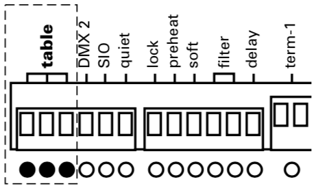
DIP switches on the front panel allow you to select EM264 options. A switch is Enabled when it is in the up position. It is Disabled when it is in the down position.
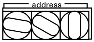 |
Setting starting addressThree rotary switches on the front panel allow you to set the starting address for the EM264. For touring systems, the starting address can be any number from 001 to 512. The starting address number for each module progresses sequentially from module to module, based on the size of the first dimmer controlled by each module. For example, in a dimming rack containing only 1kW dimmers, set the starting addresses to 001, 005 and 009. In. a dimming rack containing only 2kW dimmers, set the three EM264s to 001, 003 and 005. In. a dimming rack containing only 6kW dimmers, set the three EM264s to 001, 002 and 003. For installation systems, the starting address is the rack number. The dimmer numbering sequence for each rack is contained in configuration tables stored in the EM264’s memory.Valid addresses are 001 to 064 for installation racks. Set the rack address on the rotary switches. See Selecting configuration tables, below. Addresses 513 to 999 are used for self tests.
|
|||||||||||||||||||||||||||||||||||||||||||||||
|
|
Selecting configuration tablesThe three DIP switches labeled Table set the EM264 operating mode. If customized configuration tables have been programmed at the factory, you must enable all three switches and the rack address must be set on the rotary address switches. If a standard configuration is used, set the switches as shown on the chart below.
|
|||||||||||||||||||||||||||||||||||||||||||||||
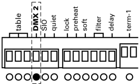 |
Enabling the second DMX512 portThe EM264 is equipped with two DMX512 input ports. If the module simultaneously receives input from both DMX512 sources, it sets dimmer output at the higher of the two levels. The second DMX512 port is activated by enabling the DIP switch labeled DMX 2. If you are only using one input, disable the switch. |
|||||||||||||||||||||||||||||||||||||||||||||||
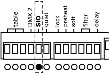 |
Enabling the SIO (Serial Input/Output) portThe SIO port is activated by enabling the DIP switch labeled SIO. The port is turned off by disabling the switch. If your system is not equipped with the SIO function, leave this switch disabled. |
|||||||||||||||||||||||||||||||||||||||||||||||
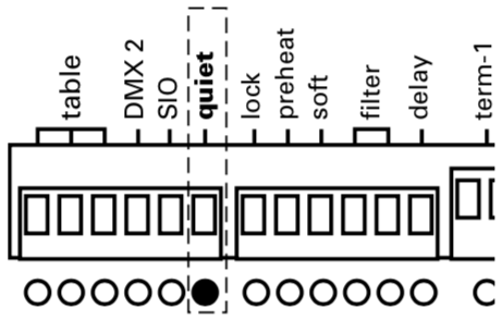 |
Enabling Quiet modeThe EM264 allows you to operate some or all of your system's dimmers in Quiet mode. Quiet mode can reduce lamp noise significantly in lamps connected to these dimmers. Available only in EM264s in L86 Installation Racks, Quiet mode is most often specified for certain dimmers at the same time the system's configuration tables are programmed at the factory. Enable the DIP switch labeled Quiet to activate Quiet mode for all dimmers programmed to use the mode. Disable the switch for normal operation.
|
|||||||||||||||||||||||||||||||||||||||||||||||
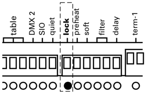 |
Enabling LockLock protects programmed information in your module. Once you have configured an EM264, you should leave it locked at all times. Before a module can be reprogrammed, you must disable Lock. Lock is activated by enabling the DIP switch labeled Lock. It is turned off by disabling the switch.
|
|||||||||||||||||||||||||||||||||||||||||||||||
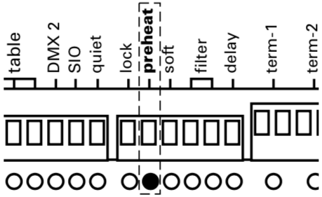 |
Enabling Preheat modeIn Preheat mode, the EM264 maintains all dimmers at a minimal level even when the dimmer output level is set to zero. This can prolong the life of your lamps. If your rack contains dimmer modules with indicator lights, Preheat mode makes the indicators glow slightly at all times. Enable the DIP switch labeled Preheat to activate Preheat mode. Disable the switch for normal operation.
|
|||||||||||||||||||||||||||||||||||||||||||||||
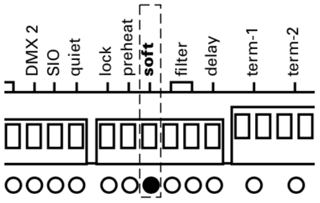 |
Enabling Soft StartSoft Start adds a filter that reduces lamp shock caused by turning a lamp with a cold bulb on to full. Soft Start checks the bulb to see if it is cold; if it is, Soft Start applies a filter to protect it. Enable DIP switch 9 to activate Soft Start. Disable the DIP switch labeled Soft for normal operation. |
|||||||||||||||||||||||||||||||||||||||||||||||
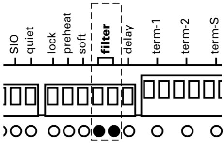 |
Enabling filteringThe two DIP switches labeled Filter set DMX512 filter levels for the EM264, as shown on the chart below. Four levels of filtering are provided to help stabilize control levels. Filter settings affect all dimmers.
|
|||||||||||||||||||||||||||||||||||||||||||||||
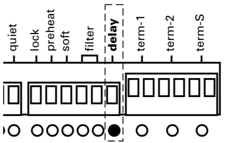 |
Setting delayIf DMX512 input is interrupted, the EM264 holds dimmer levels for either three minutes or three seconds, then fades outputs to zero. To set the delay for three seconds, disable the DIP switch labeled Delay. For a three minute delay, enable the DIP switch. The fade takes five seconds. |
|||||||||||||||||||||||||||||||||||||||||||||||
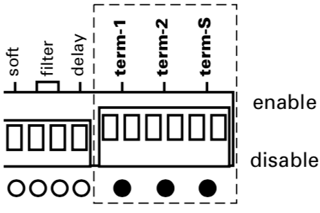 |
Control terminationThree sets of double DIP switches labeled Term-1, Term-2 and Term-s are provided to allow you to activate the control termination circuit required at the end of the DMX512 and SIO communication links. Enable all three pairs of termination switches on the highest numbered EM264 installed in the highest numbered rack in your system. Disable all three pairs of switches on the other two EM264s in that rack and all EM264s in all other racks.
|