Electronic Theatre Controls Inc

AAS Processor Unit Operation

Analog Address Specifications

The system can control up to eight analog channels wired to DMX512 dimmers. Up to eight slider stations may be installed. The system also includes a processor unit from which you can assign dimmers to channels and enter other system settings.

In addition to the eight analog channels, the system also includes a panic channel and a work light channel. Panic and work light channels gives you immediate access to emergency lights and work lights independent of the eight analog channels.

The Analog Address system includes the following features:

  • Eight analog channels
  • One panic channel
  • One work light channel
  • User-definable fade time
  • Console pile-on and disable modes
  • Diagnostic tests
  • One DMX512 input
  • One DMX512 output

Analog Address hardware components:

  • Processor unit
  • Up to eight slider stations
  • Up to eight panic stations
  • Up to eight work light stations
  • Keyswitch lockout available for all stations

Each slider station includes at least one analog channel potentiometer (pot), a take control switch, and may include any of the following:

  • Up to eight channel pots
  • Local master pot (if more than two channel pots)
  • Panic button

Menu Operation

Screen Shot 2018-11-30 at 10.47.17 AM.png

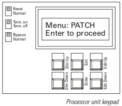
You can perform the following functions from the processor unit; each is described below.  
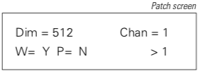
  • Assign dimmers to analog, panic and work light channels
  • Set fade time
  • Select console pile-on or disable mode
  • Select DMX512 bypass mode
  • Set DMX512 protocol termination
  • Perform diagnostic dimmer tests

Patch screen.png

Dim = Dimmer number
Chan = Channel to which dimmer is assigned
W= Y if assigned to work light channel, N if 4. not
P= Y if assigned to panic channel, N if not > Channel editing field


Assigning dimmers to analog, panic and work light channels 
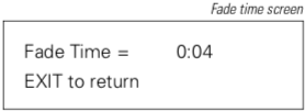
  1. Press [Exit] to activate processor unit and display menu.
  2. Scroll through menu options on LCD using Dimmer [Up] and [Down] buttons until Patch appears.
  3. Press [Enter] to display Patch screen (see illustration).
  4. Select channel number to which you want to assign dimmers by pressing Edit [Up] and [Down]. Channel numbers one through eight, W (work light), and P (panic) appear in channel editing field (see illustration).
  5. Select dimmer number you wish to assign to channel by pressing Dimmer [Up] and [Down]. Dimmer numbers stop scrolling when you reach 1; press [Up] or [Down] again to resume scrolling.
  6. Press [Enter] to record dimmer assignment. The screen displays the dimmer’s new channel assignment.
  7. Select next dimmer number to assign to channel, and press [Enter]. Repeat until all desired dimmers are assigned to channel. You may assign any number of dimmers to each analog channel, but may assign each dimmer to only one analog channel. Dimmers included in analog channels may also be assigned to panic and work light channels.
  8. Repeat steps 4 through 6 for next channel. Or, to return to menu, press and hold [Exit].
Fade time screen.png

Setting fade time

The fade time is the length of time analog channels take to fade up or down when you press [Take Control] at a slider station. Fade time applies to all analog channels and the work light channel. Panic channel turns on instantly.

Follow these steps to set fade time:

  1. Press [Exit] to display menu.
  2. Scroll through menu options on LCD using Dimmer [Up] and [Down] until Fade Time appears.
  3. Press [Enter] to display the Fade Time screen (see illustration).
  4. Press Edit [Up] and [Down] to set the desired fade time. You may enter a fade time between 0:00 seconds and 5:59 minutes.
  5. Press and hold [Exit] to save selection and return to menu.
Console mode screen.png

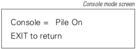
Selecting console pile-on or disable mode

If you have a lighting control console wired into the Analog Address system, you can choose whether or not the console can control dimmers included in analog channels.

Two console control options are available: pile-on and disable. If you select pile-on, the console is able to control all dimmers included in Analog Address channels; the highest setting between the console and Analog Address establishes active levels. If you select disable, the console is not able to control any dimmers included in analog or panic channels; the console can still control dimmers included in only the work light channel. In disable mode, console controls all dimmers not included in Analog Address analog or panic channels.

To select console control mode, follow these steps:

  1. Press [Exit] to display menu.
  2. Scroll through menu options on LCD using Dimmer [Up] and [Down] until Console appears.
  3. Press [Enter] to display the Console mode screen (see illustration).
  4. Press Edit [Up] and [Down] to select pile-on or disable.
  5. Press [Exit] to save selection and return to menu.
 

Selecting bypass mode

The bypass switch on the processor unit allows you to disable the Analog Address system, and to permit DMX512 data to pass directly from the console to the dimmers. You may choose to use bypass if you want only the console to control dimmers, or if the Analog Address system malfunctions.

To enter bypass mode, set bypass switch to Bypass. To resume normal operation, set bypass switch to Normal.


Selecting DMX termination or normal modes

The terminate switch on the processor unit terminates a DMX512 signal from a remote control console. The processor unit combines the incoming DMX512 data with the Analog Address data, and generates a new DMX512 signal.

The Analog Address system is normally the last receiver on a DMX512 data stream. If so, set the Termination switch to Terminate on. If your Analog Address system is not the last receiver, set the switch to Terminate off.


Monitor test screen.png

Performing diagnostic tests

Three diagnostic tests are available from the processor unit: Test one, Test all and Monitor.

Test one and Test all
Allow you to set one or all dimmers at a specific output level directly from the processor unit.

Monitor

Displays which control station currently has control, if panic and work light channels are active, and if the processor unit is receiving data from a control console. Monitor also displays current output levels for all analog channels.

To perform diagnostic tests, follow these steps:

  1. Press [Exit] to display menu.
  2. Scroll through menu options on LCD using Dimmer [Up] and [Down] until test name appears, Test one, Test all or Monitor.
  3. Press [Enter] and hold until LCD displays test screen.
  4. Test one:
    Press Dimmer [Up] and [Down] to select desired dimmer number.

    Press Edit [Up] and [Down] to select dimmer output level. Or, to set dimmer at 100 percent, press [Enter] , Edit [Up]. To set dimmer at 0 percent, press [Enter], Edit [Down]. Press [Enter] again to return to the menu.

    Test all:
    Test allows you to control output of all dimmers. When you enter Test all, Analog Address turns all dimmers off until you enter an output level.

    Press Edit [Up] and [Down] to select output level.

    Monitor:
    When in Monitor test, the following information appears (see illustration).

    T = (Take Control) indicates which control station currently has control of channels.
    P = (Panic) indicates if panic channel is active (Y for yes, N for no).
    W = (Work light) indicates if work light channel is active (Y for yes, N for no).
    D = (Data) indicates if the control panel is receiving data from a console (Y for yes, N for no).

    The bottom row of numbers displays the level that each channel is currently outputting. The first two digits indicate channel 1’s output level; the third and fourth digits indicate channel 2’s output level, etc. If channel output is 100 percent, the level digits read FF.

    In the illustration above, slider station 1 has control; the panic channel is active; the work light channel is not; and the processor unit is receiving data from a console. Channels 1 and 2 are outputting at 90 percent, channel 3 at 75, channel 4 at 100 percent, and the remaining channels are off.

  • Was this article helpful?