Generate Defaults Sensor CEM Classic-All Versions
A CEM uses a configuration EEPROM to hold its memory indefinitely. Generating defaults is only needed when a CEM is placed in a different rack requiring a different config or the config is corrupted. Working memory holds Backup looks, Recorded Loads (AF Systems only) and is held with capacitors. When unpowered for more than 3 months, a CEM will lose the working memory data and show an error until those capacitors are recharged (about 4 hours).
In a Sensor Classic system, all racks store a copy of the configuration. If you have one rack with a problematic processor, consider transferring the config from a working rack instead, or transfer the config after performing the steps below.
Rewriting a custom configuration requires a site visit from an experienced authorized service provider with specialty equipment. If your rack has a mix of module types, a custom config, or anything other than a 1:1 patch with D20s, and you have a single rack system, contact ETC technical services before proceeding.
CAUTION:
- You cannot accurately generate defaults if there is a mixture of dimmer types in a given rack.
- In CEM software version 2.x or below, you cannot generate defaults if there are different size racks linked together with ETCLink. (In the case of multiple-rack setups connected via ETCLink, you generate defaults in one rack, then download that configuration at all other racks.)
- Backup Looks, and AF System Recorded Loads will be lost when generating defaults.
- Tapping [Setup] during the generation process provides additional menu options; Only do this with an ETC technician on the phone.
- There are tests in the diagnostic tests menu that can make your CEM inoperable. In many cases the CEM would need to come back to the factory for repair.
- The key to successfully generating defaults is not deviating from the instructions below.
Notes:
- Packs and racks are sold by how many circuits they have; yet they are configured by how many single density module slots they have. Some modules have 1 or 2 circuits to them. Others may take up two module slots. This is why the circuit configuration does not always match the rack label.
- Generally speaking use [Enter] key to enter a sub-menu and to confirm. When confirming a menu item, asterisk (*) indicates what will be saved in v3.xx.
- In a multi-rack system it is good practice to generate defaults in rack 1 and transfer the configuration to the other racks.
Sensor CEM Generate Defaults Instructions software v3.XX
CAUTION: Read ALL notes at the top of the page!
This process erases all system configuration data. Do not use this instruction set if you have a custom patch or different types of dimmer modules with in the same rack. If your racks and module types are not identical, you will need to hire an ETC Authorized Field Service Provider from a local service center to configure the system.
Note: When in this setup mode, the buttons may feel like they are not working. If the button doesn't react when you press it, hold the button down until it takes your command.
Written instructions are below this video, or follow along here:

Step 1:
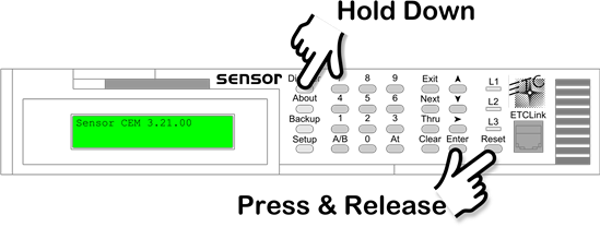
- Enter diagnostic tests by holding down [Dimmer] and tapping [Reset] once. Continue holding [Dimmer] for approximately 10 seconds after releasing [Reset]. You can release the [Dimmer] button when you see “Password Received” flash on the screen quickly.
Step 2:
- Use [↑] or [↓] or press [4] [1] to select "41-Generate Defaults" and then press [Enter].
Step 3:
- "Overwrite Configuration? NO" appears on the LCD. Use [↑] or [↓] to scroll "NO" to "YES" and press [Enter] to confirm. (for these actions you will have to hold the buttons slightly so the actions happen)

Note: The processor will display several process messages while configuring. When the configuration process is complete, the LCD will display "Setup System Number of Racks:1*"
Step 4:
- Enter the number of racks in the system with the [↑] or [↓] keys or type a number with the CEM keypad. Press [Enter] to confirm, then [→] to continue.
Note: The number of racks in the system should be the number of racks that are ETCLinked together. If racks are not linked together (e.g. most portable rack configurations), each CEM is its own one rack system.
Step 5:
- Set the type of rack used in the default setup. Press [Enter] then scroll to the desired rack type with [↑] or [↓]. Press [Enter] to confirm then [→] to continue.
Note: SP racks refer to Portable/Touring racks and SR racks refer to Install racks. The number of the rack refers to the number of standard module slots in the rack, NOT the # of circuits. Also note that many rack types are listed twice, once with just their name (e.g. "SR48"), and a second time with "bal" following the name ("SR48 bal"). A rack that numbers the dimmers in order "1,2,3,4,5,6 . . ." is a straight rack and uses the first listing ("SR48"). A rack that numbers the dimmers by groups of two "1,2,7,8,13,14 . . ." balances the load across the phases and uses the second listing ("SR48 bal"). Most portable packs and touring racks are straight.
Step 6:
- Enter the rack type using the [↑] or [↓] keys, select the CEM type that applies (e.g. "Setup CEM Type: CEM 120v"). Press [Enter] to confirm then [→] to continue.
Step 7:
- Press [Enter], then type the # to the desired Unique Dimmer # with the keypad or [↑] or [↓] keys. Press [Enter] to confirm then [→] to continue.
Note:
- Do not duplicate unique dimmer numbers.
- In v3.10 & 3.11 do not use unique dimmer numbers in the range of 5530 - 5535 these will cause the CEM to reset after any attribute is changed. Using UD# 5533 will cause the CEM to get caught in a reset loop and repair is required to fix it.
- In v3.10 and below the unique dimmer number is set by the configuration this means it cannot be changed during the generate defaults process.
Step 8:
- Setup Module type lets you select one dimmer module type for the entire rack. Scroll to the desired module with [↑] or [↓] keys. Press [Enter] to confirm then [→] to review all the settings for this rack.
SPECIAL NOTE for Multi-rack Systems:
If step 4 (above) includes more than 2 racks you must hit [Next] to configure the setting for additional racks, follow steps 5-8 then using [Next] to advance to the next rack. Do this as many times as needed to configure each rack. Between racks, the CEM will display several configuration process messages. The configuration in CEM software v3.xx and above can contain a different rack size, as long as the module type is the same in the entire rack.
Step 9:
- Press [Exit] to confirm your default configuration and write it to memory.
Step 10:
- If the rack (Step 8: above) has advanced features (AF) capable modules, the CEM will ask if you would like to use this mode. Using [↑] or [↓] keys, choose "YES" or "NO". Press [Enter] to confirm.
Note: If you did not choose an AF module, this step will not be displayed. If there are AFM blank modules in the rack answer "NO".
Step 11:
- Select the ETCLink Address for this CEM with [↑] or [↓] or the number keypad and press [Enter] to complete the default CEM configuration setup.
Note: The CEM will display several processing messages while initializing data. When complete it will return to the home screen.
Step 12:
- If there are multiple racks in the ETCLink group, go to the next rack and set the ETCLink number and transfer the config from rack 1, to rack 2. Continue to do this in order through all the racks. This is done in [Setup] [2]-Rack [→] [→]..... "Setup Rack Transfer Local Rack Addr:1*" and follow the prompts.
Step 13:
- Test the system for desired functionality.
Note: The default configuration will enable only port A with the first DMX address for the rack matching the unique dimmer number set in step 7. If your system uses port B (e.g. for a Unison architectural system), you will need to re-enable DMX port B after generating defaults. This is done in [Setup] 2-Rack [→] [→].... find DMX B and enable it.
General Touring Rack Information
| Sensor Touring Racks | Rack Configured as | Rack Frame Size | Dimmer Module Types |
|---|---|---|---|
| 48 x 2.4k | SP24/ESP24 | Small Frame | D20 |
| 96 x 2.4k | SP48/ESP48 | Double Small or Large Frame | D20 |
| 24 x 6k | SP24/ESP24 | Small Frame | D50 |
| 48 x 6k | SP48/ESP48 | Double Small or Large Frame | D50 |
| 12 x 12k | SP24/ESP24 | Small Frame | D100 |
| 24 x 12k | SP48/ESP48 | Double Small or Large Frame | D100 |
| Sensor Portable Pack | Rack configured as | Rack Frame Size | Dimmer Module Types |
|---|---|---|---|
| 24 x 2.4k | SP12/ESP12 | 12 Module Chassis | D20 |
| 12 x 2.4k | SP6/ESP6 | 6 Module Chassis | D20 |
| 12 x 6k | SP12/ESP12 | 12 Module Chassis | D50 |
| 6 x 6k | SP6/ESP6 | 6 Module Chassis | D50 |
| 6 x 12k | SP12/ESP12 | 12 Module Chassis | D100 |
| 3 x 12k | SP6/ESP6 | 6 Module Chassis | D100 |
Sensor CEM Generate Defaults Instructions software v2.XX
CAUTION: Read ALL notes at the top of the page!
This process erases all system configuration data. Do not use this instruction set if you have a custom patch or different types of dimmer modules or sizes of dimmer racks. If your racks and module types are not identical, you will need to hire an ETC Authorized Field Service Provider from a local service center to configure the system.
Note: When in this setup mode, the buttons may feel like they are not working. If the button doesn't react when you press it, hold the button down until it takes your command.
Written instructions are below this video, or follow along here:

Step 1:
- Enter diagnostic tests by holding down [Dimmer] and tapping [Reset]. Continue holding [Dimmer] for approximately 10 seconds after releasing [Reset]. You can release the [Dimmer] button when you see “Password Received” flash on the screen quickly..
Step 2:
- Use [↑] or [↓] or press [4] [1] to select "41-Generate Defaults" and then press [Enter].
Step 3:
- Select the Rack and Module Types and if the rack is Balanced ("Bal") by scrolling using the [↑] or [↓]. (As you scroll the list of modules will change to append "Bal", as you go farther the rack type will change, and as you continue farther it will change between portable and install). This list is very long so continue to scroll.
Note: SP racks refer to Portable/Touring racks and SR racks refer to Install racks. The number of the rack refers to the number of module slots in the rack NOT the # of circuits. Also note that many rack types are listed twice, once with just their name (e.g. "SR48"), and a second time with "bal" following the name ("SR48 bal"). A rack that numbers the dimmers in order "1,2,3,4,5,6 . . ." is a straight rack and uses the first listing ("SR48"). A rack that numbers the dimmers by groups of two "1,2,7,8,13,14 . . ." balances the load across the phases and uses the second listing ("SR48 bal"). Most portable packs and touring racks are straight.
Step 4:
- Enter the number of racks in the system with the number keypad and press [Enter].
Note: All racks in the ETCLink group must be the same size and type. The number of racks in the system should be the number of racks that are ETCLinked together. If racks are not linked together (e.g. most portable rack configurations), each CEM is its own one rack system.
Step 5:
- "Erase current rack? press EXIT to abort" appears on the LCD, press [Enter].
Note: The CEM will display several process messages during configuration.
Step 6
- If the rack (Step 3: above) has advanced features (AF) capable modules, the display will show "press 1 for ADVANCED FEATURES rack". Press [1] or [→] to continue.
Note: If you did not choose an AF module, this step will not be displayed. If there are AFM modules in the rack press [→] to continue.
Step 7:
- "Select the number of racks" appears on the LCD. Type a number with the keypad and press [Enter].
Step 8:
- "rack ### Sure? Enter or Exit" appears on the LCD. Press [Enter].
Note: The CEM will display several process messages during configuration. When complete it will return to the home screen.
Step 9:
- If there are multiple racks in the ETCLink group, go to the next rack and set the ETCLink number and transfer the config from rack 1, to rack 2. Continue to do this in order through all the racks. This is done in [Setup] [2]-Rack "load config from" appears on the CEM LCD and follow the prompts.
Step 10:
- Test the system for desired functionality.
General Touring Rack Information
| Sensor Touring Racks | Rack Configured as | Rack Frame Size | Dimmer Module Types |
|---|---|---|---|
| 48 x 2.4k | SP24/ESP24 | Small Frame | D20 |
| 96 x 2.4k | SP48/ESP48 | Double Small or Large Frame | D20 |
| 24 x 6k | SP24/ESP24 | Small Frame | D50 |
| 48 x 6k | SP48/ESP48 | Double Small or Large Frame | D50 |
| 12 x 12k | SP24/ESP24 | Small Frame | D100 |
| 24 x 12k | SP48/ESP48 | Double Small or Large Frame | D100 |
| Sensor Portable Pack | Rack configured as | Rack Frame Size | Dimmer Module Types |
|---|---|---|---|
| 24 x 2.4k | SP12/ESP12 | 12 Module Chassis | D20 |
| 12 x 2.4k | SP6/ESP6 | 6 Module Chassis | D20 |
| 12 x 6k | SP12/ESP12 | 12 Module Chassis | D50 |
| 6 x 6k | SP6/ESP6 | 6 Module Chassis | D50 |
| 6 x 12k | SP12/ESP12 | 12 Module Chassis | D100 |
| 3 x 12k | SP6/ESP6 | 6 Module Chassis | D100 |
Sensor CEM Generate Defaults Instructions software v2.XX MORE IN DEPTH SETTINGS. USE STEPS ABOVE FOR STANDARD SETTINGS.
CAUTION: Read ALL notes at the top of the page!
This process erases all system configuration data. Do not use this instruction set if you have a custom patch or different types of dimmer modules or sizes of dimmers racks. If your racks and module types are not identical, you will need to hire an ETC authorized field service provider from a local service center to configure the system.
Note: When in this setup mode, the buttons may feel like they are not working. If the button doesn't react when you press it, hold the button down until it takes your command.
Step 1:
- Enter diagnostic tests by holding down [Dimmer] and tapping [Reset]. Continue holding [Dimmer] for approximately 10 seconds after releasing [Reset]. You can release the [Dimmer] button when you see “Password Received” flash on the screen quickly.
Step 2:
- Use [↑] or [↓] or press [4] [1] to select "41-Generate Defaults", and then press [Enter].
Step 3:
- Select the Rack and Module Types and if the rack is Balanced ("Bal") by scrolling using the [↑] or [↓]. (As you scroll the list of modules will change to append "bal", as you go farther the rack type will change, and as you continue farther it will change between portable and install). This list is very long, so continue to scroll.
Note: SP racks refer to Portable/Touring racks and SR racks refer to Install racks. The number of the rack refers to the number of standard module slots in the rack NOT the # of circuits. Also note that many rack types are listed twice, once with just their name (e.g. "SR48"), and a second time with "bal" following the name ("SR48 bal"). A rack that numbers the dimmers in order "1,2,3,4,5,6 . . ." is a straight rack and uses the first listing ("SR48"). A rack that numbers the dimmers by groups of two "1,2,7,8,13,14 . . ." balances the load across the phases and uses the second listing ("SR48 bal"). Most portable packs and touring racks are straight.
Step 4:
- Press [Setup].
Step 5:
- "Number of Racks required: (1-63)" appears on the LCD. Enter the number with the keypad and press [Enter].
Step 6:
- "Erase current racks? Press EXIT to abort" appears on the LCD, press [Enter].
Step 7:
- If the rack (Step 3: above) has advanced features (AF) capable modules, the display will show "press 1 for ADVANCED FEATURES rack". Press [1] or [→] to continue.
Note: If you did not choose an AF module, this step will not be displayed. If there are AFM modules in the rack press [→] to continue.
Step 8:
- "Enter Full On Output Voltage (0-140)" appears on the LCD. Enter the proper voltage with the keypad (e.g. [1] [2] [0]) and press [Enter].
Step 9:
- "1=Panics With Hold Type Switch" appears on the LCD. Press [Enter] (LEAVE at default do not change)
Step 10:
- "1=220V Rack" appears on the LCD. If this is an HCEM, press [1], otherwise press [Enter].
Step 11:
- "1=Dimmers Setup For Mux. Type Lamps" appears on the LCD. If the entire rack is dimmer-doubled, press [1] otherwise, press [Enter]
Step 12:
- "Ports 0-A,B 1-A+B 2-A 3-B 4-off" appears on the LCD. Use the keypad to enter the appropriate choice from the list below. (most common is [1] Pile on)
- 0 - A,B - DMX A takes precedence over DMX B
- 1- HTP DMX A + DMX B also known as Pile On (most common)
- 2- DMX A only
- 3- DMX B only
- 4- off (No DMX)
Step 13:
- "Data Hold Time (sec) 0-600 0-HOLD" appears on the LCD (How long the CEM will hold the last look when DMX drops out), usually [Enter] for default.
Step 14:
- "1=Panic Switches Enabled" appears on the LCD, press [Enter].
Step 15:
- "Select Rack Number:" appears on the LCD. Type the appropriate rack number and press [Enter].
Step 16:
- "Rack ### Sure? Enter or Exit" appears on the LCD, press [Enter].
Note: The CEM will display several process messages during configuration. When complete it will return to the home screen.After the steps described above are carried out, the pictures will be immediately deleted without any additional confirmation queries.
Step 17:
- If there are multiple racks in the ETCLink group, go to the next rack and set the ETCLink number and transfer the config from rack 1, to rack 2. Continue to do this in order through all the racks. this is done in [Setup] [2]-Rack "load config from" and follow the prompts.
Step 18:
- Test the system for desired functionality.
| Sensor Touring Racks | Rack Configured as | Rack Frame Size | Dimmer Module Types |
|---|---|---|---|
| 48 x 2.4k | SP24/ESP24 | Small Frame | D20 |
| 96 x 2.4k | SP48/ESP48 | Double Small or Large Frame | D20 |
| 24 x 6k | SP24/ESP24 | Small Frame | D50 |
| 48 x 6k | SP48/ESP48 | Double Small or Large Frame | D50 |
| 12 x 12k | SP24/ESP24 | Small Frame | D100 |
| 24 x 12k | SP48/ESP48 | Double Small or Large Frame | D100 |
| Sensor Portable Pack | Rack configured as | Rack Frame Size | Dimmer Module Types |
|---|---|---|---|
| 24 x 2.4k | SP12/ESP12 | 12 Module Chassis | D20 |
| 12 x 2.4k | SP6/ESP6 | 6 Module Chassis | D20 |
| 12 x 6k | SP12/ESP12 | 12 Module Chassis | D50 |
| 6 x 6k | SP6/ESP6 | 6 Module Chassis | D50 |
| 6 x 12k | SP12/ESP12 | 12 Module Chassis | D100 |
| 3 x 12k | SP6/ESP6 | 6 Module Chassis | D100 |